Here I will document the progress made on the 2nd gen 5E-FE intake manifold upgrade. Everything will be listed in reverse order so the newest news is always at the top.
6/12/07
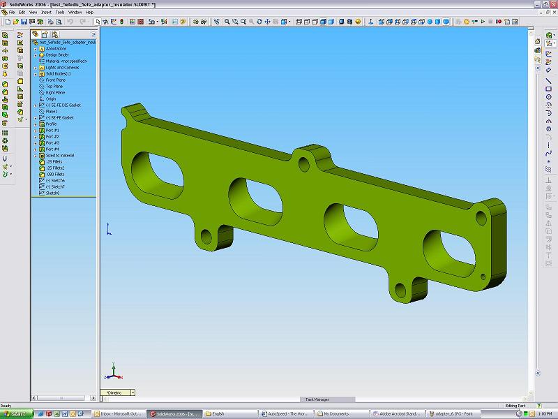
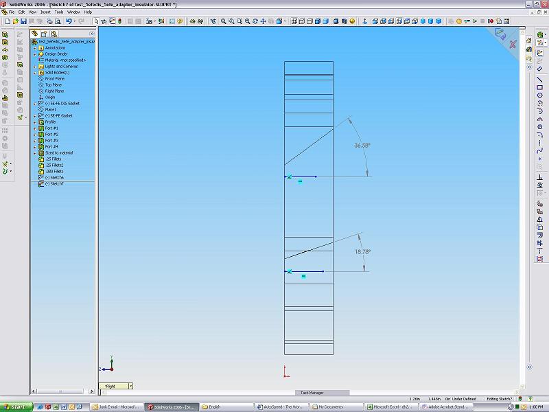
All of the tests still need to be run with the stock 5E-FE DIS intake manifold on the car. However, I have found time to finish making the adapter flange for the ACIS intake manifold. I'm pretty happy with how it turned out. We'll have to wait and see how well it ends up working out though.
3/15/07
Well, its been quite the break from this project, but its back now. And, its being picked up right where it left off. So, I'm thinking now would be a good time to elaborate on my testing procedures. I have two tests lined up to prove if this adapter and manifold is going to be worth while.
First off is testing when the stock manifold's runners become a restriction. To do this I'll be using a magnehelic differential pressure gauge. For those of you who don't know, this is basically a vacuum/pressure gauge. The one I have measures up to 30 inches of water or roughly 1 psi. For those of you who don't know how vacuum effects engine performance I highly suggest you read up on it. It is a key aspect of engine operation, performance and effeciency.
The idea of a differential pressure gauge is that you hook it up at two different points and it measures the (in this case) vacuum difference between the two points. As a simple example say we want to measure the vacuum increase across an air filter. To do this, you simply take a vacuum reading from in front of the air filter and one from in back. Then, you subtract one from the other and that is your vacuum increase across the filter. This is exactly how much of a restriction the air filter is creating and can be converted into a horsepower number. Here is a picture to represent what I'm talking about.
These vacuum measurements (which are made up) are taken at WOT (wide open throttle) so the engine is sucking as much air as it can. As we can see here, the air filter creates a restriction in the intake system. Having to suck air through the filter slows the air down and thus we have more vacuum on the end closer to the engine than on the far side of the filter. This creates 5 inches of water vacuum (thats what the gauge would read). If we were to remove the filter, the restriction would be gone and both sides would read 2 in/water. This means there will be more air flowing into the engine and thus more power.
For example, think of sucking air through a straw. The vacuum should be equal throughout the straw. Now, stick something into the straw and suck. The vacuum is going to be higher on the side you are sucking than the far side. Its the same thing here.
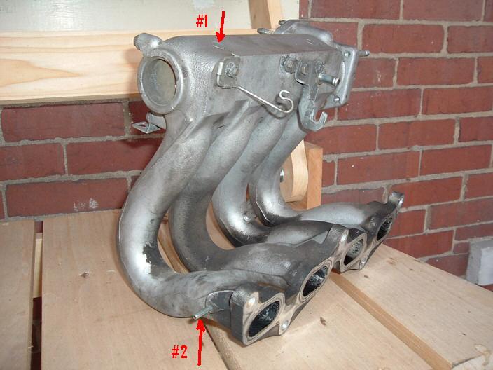
So, this is pretty much what I plan to do with the 5E-FE DIS intake manifold. The only difference here is that the runners are creating the restriction this time. So, we simply place a vacuum tube in the intake manifold plenum (#1), and another at the base of the runner very close to the head (#2). The gauge will measure if there is any difference in vacuum between the plenum and runner base and thus if the runners are creating a restriction in the intake system. When making a run at WOT this should who us exactly when the runners become a restriction and how much of a restriction they become. With a little calculation we should be able to see how much horsepower is lost because of this as well.
To show you how this works lets use the above example of the air filter restriction. No vacuum means no restriction (this is impossible btw since theres always some restriction) and every once of air gets into the engine. Full vacuum means total restriction and no air getting into the engine. Full vacuum is 14.7 psi depending on altitude etc. Lets do a little conversion because we are measuring vacuum in inches of water, not psi. 14.7 psi = 406.9 in/water. So lets plug in the numbers from the air filter example above. If 0 in/water = 100% air and 406.9 in/water = 0% air then we should be able to calculate how much 5 in/water is.
5 / 406.9 = .012 = 1.2% less air getting into the engine
Since the amount of air is proportional to how much power your engine makes this can also be translated to 1.2% power loss through the air filter in the example above. Keep in mind this is a rough estimate because there are tons of other variables in play here.
Typical car intake systems (measured from the throttle body out) have anywhere from 10 - 30+ inches of water at max throttle and max rpm. Free flowing cold air intakes usually alleviate this restriction and thus you get more horsepower.
The second test is quite a bit easier to wrap your head around. This test is just measuring torque (and horsepower) output before and after the ACIS manifold installation. This will be done with a G-Tech. It will output a complete torque graph and show the baseline as well as the modified state. This way we can see the exact gains or losses in the system.
1/17/07
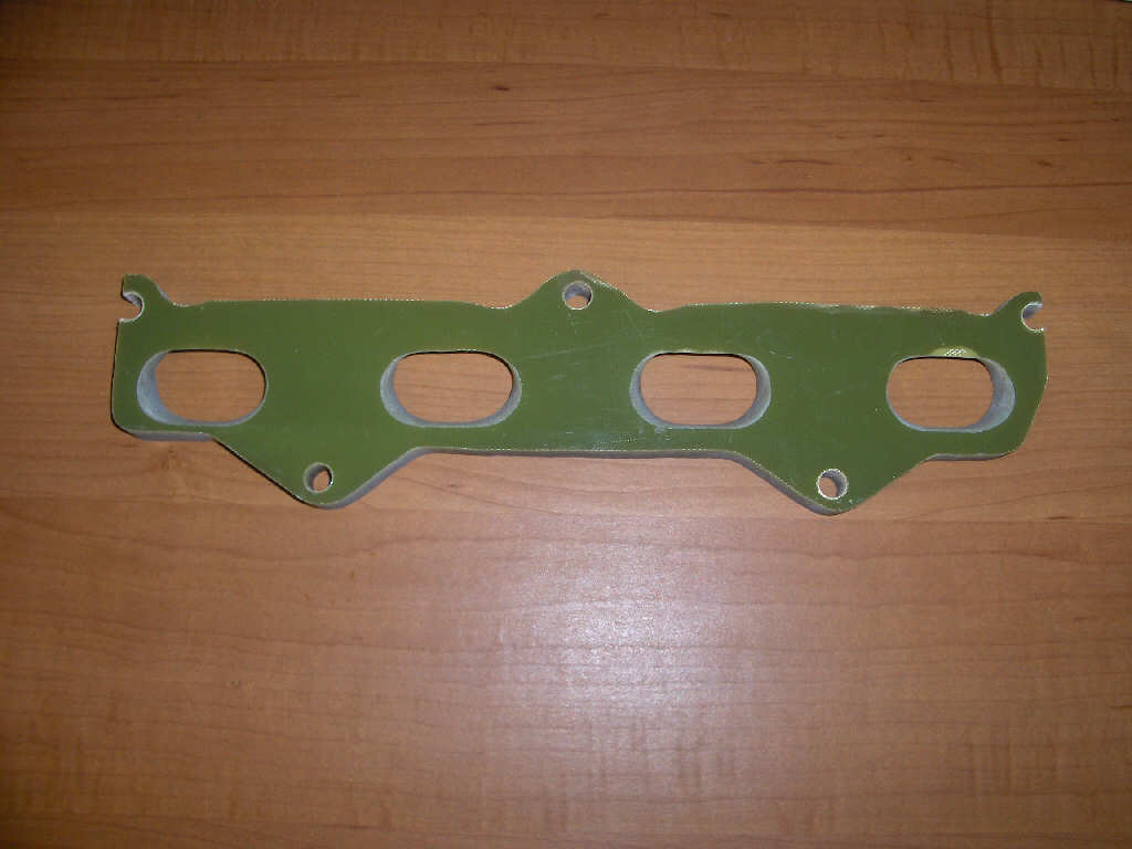
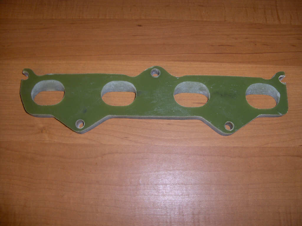
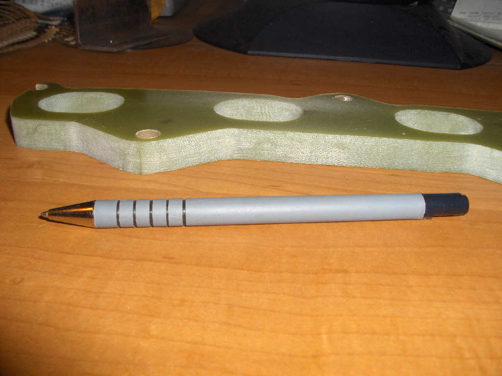
I ended up finding a 5E-FHE ACIS intake manifold for fairly cheap so I decided to pick it up. Pending more testing this will be used and evaluated as an upgrade for the 2nd gen 5E-FE. However, to mate this manifold up to the 2nd gen 5E-FE an adapter plate will need to be made because the ports do not match up. I've talked with others on this exact subject and now that I have the manifold I can go ahead with it. The adapter plate will be made out of the same phenolic material that the intake manifold insulators are made of. This will keep the manifold cool as well as create the transistion between port shapes. There are some pictures of what the adapter might look like below.
11/22/06
It has been decided not to go ahead on this project until testing has been done to ensure that the intake manifold is a restrictive part of the intake system. So, I have procured an extra intake manifold for modification and testing from Alfradio on TercelOnline.com for this testing. He'll be shipping it out once he recieves his current intake manifold back from Jet Hot coating.
This testing will read vacuum at the base of the runners (head side) while at full throttle, and compare that to vacuum in the intake manifold plenum. If there is vacuum (at full throttle) at the base of the runners, but no vacuum in the plenum we know for sure that the intake manifold is a definite restriction and that it needs to be opened up for more power. We can also see at what rpm the intake manifold starts to create a restriction and control our powerband from there.
The manifold will need to be modified for testing. This will be done by drilling and pressing in a small tube at the base of the runner. Off of the tube a vacuum gauge will be hooked up to show the runner's vacuum. To read the plenum vacuum another vacuum line will be run off a port off the plenum to another vacuum gauge.
6/20/06
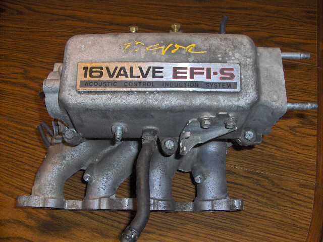
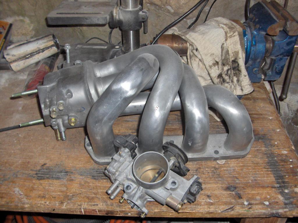
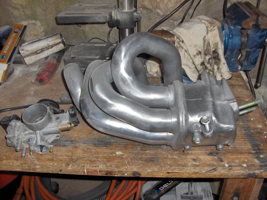
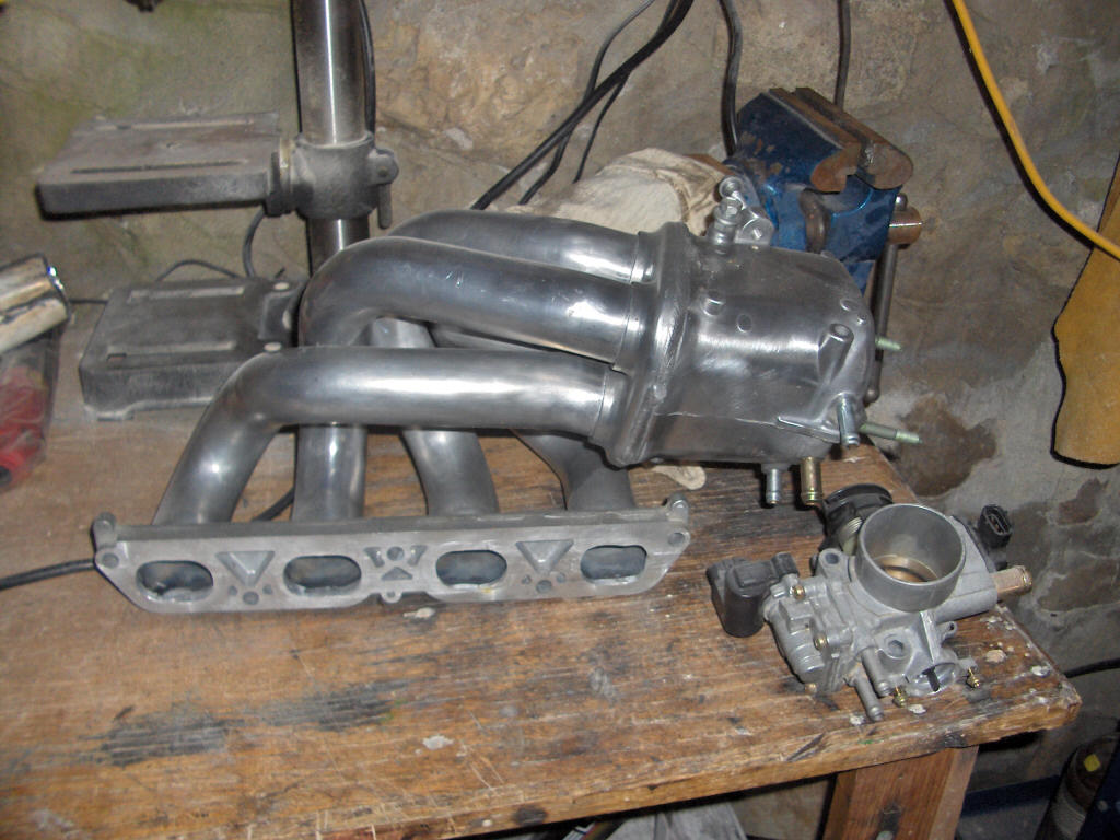
A little history here first. To be quite honest this is a project that has been going on for a long time now. If you ever really take a good look at the 2nd gen 5E-FE's intake manifold you can see that the thing is just going to choke your engine at high rpms. I have searched around for ways to bore/hone the manifold without spending loads. I have also looked at alternate intake manifolds that could be used. For this project I ended up settling on another Toyota intake manifold that will be modified to fit the 2nd gen 5E-FE. The manifold comes from a first generation 1ZZ-FE engine. This can be found in the 1999 to 2002 Corollas. Upon looking back it probably would be easier to convert an intake manifold from a 1st gen 5E-FE or the ACIS 5E-FHE intake manifold, but thats just not how I went with this.
Here are some pictures of the intake manifold. It has already been modified. It previously had a weld bead in the ID of each tube... I don't know why Toyota left it like that but it was a fairly large bead and must have created turbulance, and thats something you definitly do not want right before the going into the head. It also had a nice recess after the weld bead. That was filled in and the face was milled flat. You can see in the 3rd picture that the ports are not totally cleaned up yet.