So I finally collected too many pictures to just keep listing them. Here I will document the progress made on the 3E-E header. Everything will be listed in reverse order so the newest news is always at the top.
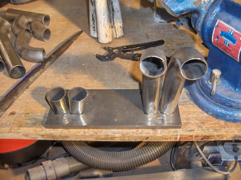
10/20/06
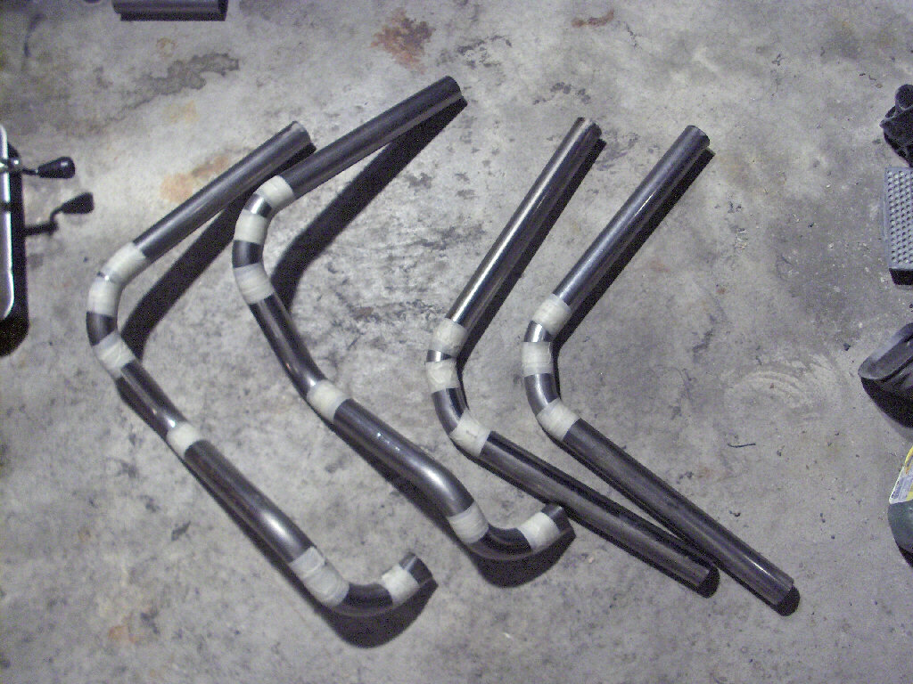
The past week I had some time to get my hands dirty with the 3E-E header again. I was able to cut up the steel for all the runners and do some test fitting. I also mocked up the header by taping the cut up pieces all together. Things will definitly need to be ground down to fit all nice and tidy, but it is all comming together very nicely. I'm hoping to be able to tack it together soon and then decide weather I'm going to weld it myself or take it somewhere and have it welded professionally. For now I have pictures of the mocked up runners.
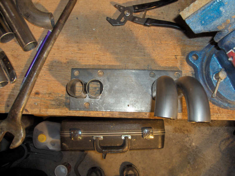
4/17/06
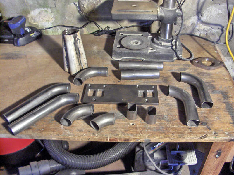
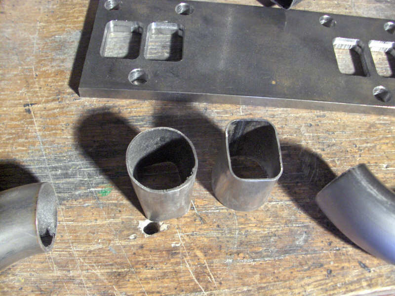
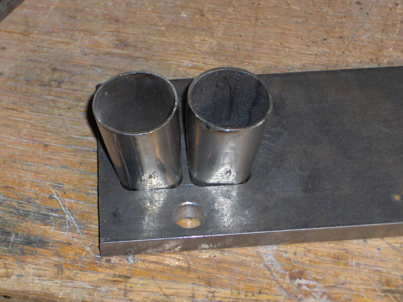
Lets start putting things together already, right? Well, heres a start. I gathered all the pieces I had already cut and formed and laid them out. You can see the transition pieces that will fit into the flange. I test fit these pieces and formed them to fit better because I had made them before I had the flange cut out. After that I took them and welded the inside of the tube and flange. Of course this leaves a big weld bead in the flow of the exhaust. In comes the die grinder to remove that material. It will be all smooth when I am done.
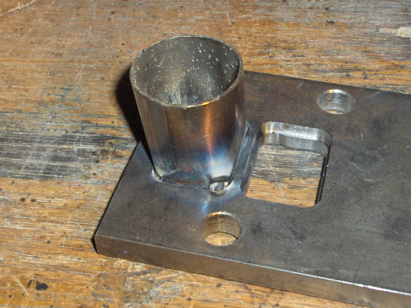
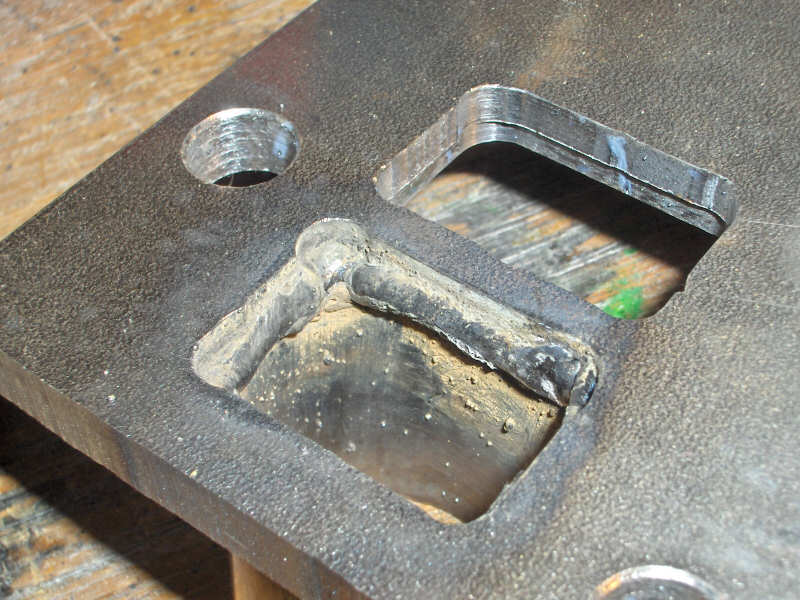
3/21/06
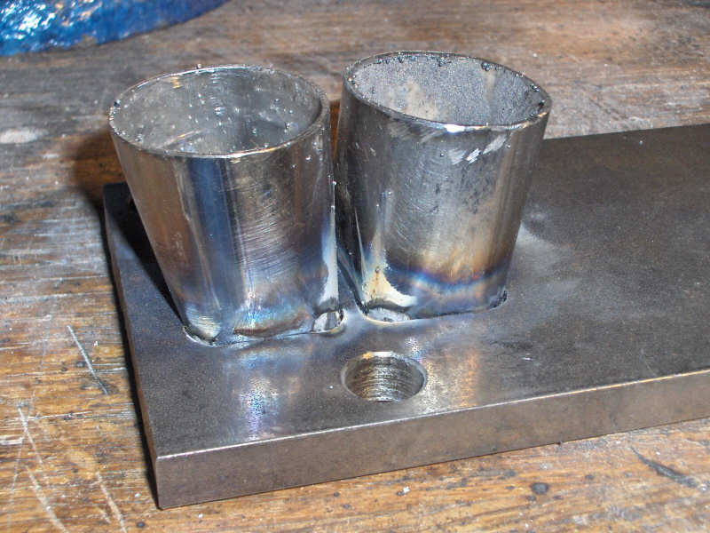
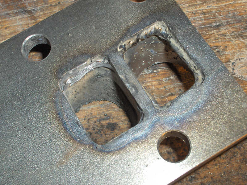
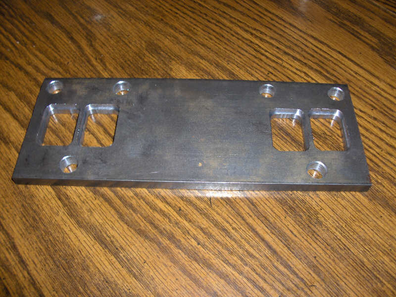
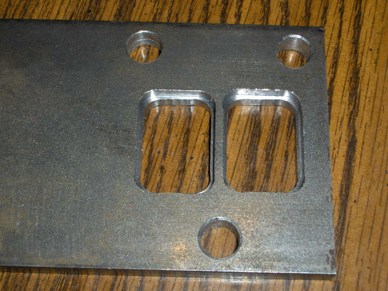
The steel for the flange has finally arrived. So, I found some time to drill the mounting holes for it. In the following week I took it to work and milled out the ports on a old manual Bridgeport mill. I then counterbored the ports to let the pipe sit into the flange to create a stronger joint between the pipe and flange. The joint here is important because it is where the heat is most intense as well as there being a lot of stress on the header from the weight of the rest of it hanging.
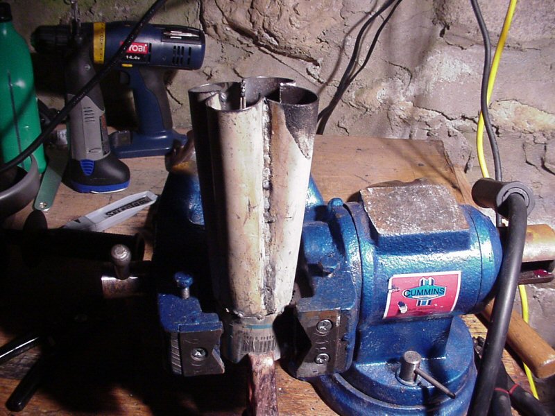
So I have ordered the material. While waiting for it to come in I pulled some 2" straight tubing I had and chopped it up to form the collector. A lot of pounding with a hammer later and we have the 4 pieces needed to weld together to make the collector. I tack welded all the 4 pieces to a short piece of 2" tubing so they would line up. Then I welded them all together outside. I did some internal welding but the space is very limited and it didn't work out all that great. After welding the collector up, I took it to work the next day and used a 1/2" pneumatic belt sander to smooth out the rough weld bead on the inside of the collector.
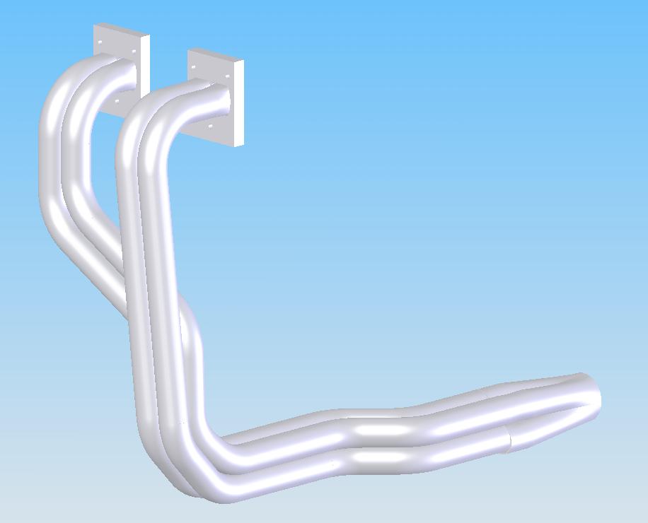
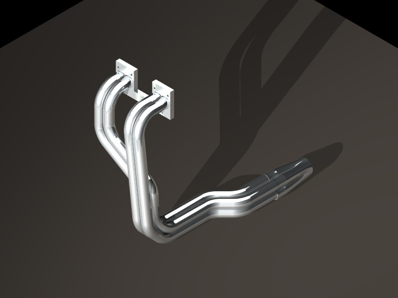
We start out with researching a lot. Mostly on the internet reading lots of articles and differnet websites. My most useful information has come from HeadersbyEd.com. I purchased his infopak and read through it. Everything he says makes sense even though it does contradict things you will read. From the information I have gathered I have decided on a 4-1 long tube sytle header. Here are some pictures of the initial designs drawn up in SolidWorks. The second picture was run through rendering software to imitate a chrome look.