BACK
ACIS Intake Manifold Installation
Written by: Terseoman
Additional content by: Paseo92
It's a fairly simple procedure if you know your motor stuff. This overall took me about 3 hours. Thats with uninstalling the old intake, installing the new one, and getting the vacuum done.
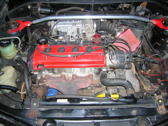
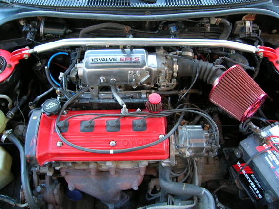
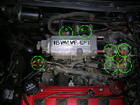
STEP 1 - The old JDM 5E-FE with intake.
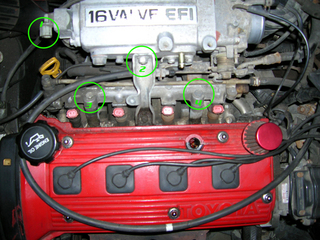
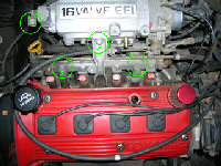
STEP 2 - Removal of fuel rail, IAC (Idle Air Controller), and intake support
Circle #1 : Unplug the Idle Air Controller.
Circle #2 : Unbolt the Intake Support (12mm - 1 nut, 1 bolt)
Circle #3 and Circle #4 : Unbolt the Fuel Rail (12mm x 2)
NOTE FOR FUEL RAIL: The spacers (cylindrical pieces the bolts go through) sit freely on the head. Make sure not to drop them!
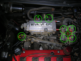
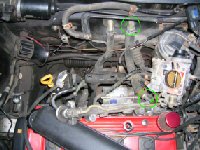
STEP 3 - Removal of throttle body, and various vacuum lines
Circle #1 to Circle #4 : Unbolt the Throttle Body (12mm - 2 nuts, 2 bots)
Circle #5 : Disconnect the Vacuum Line going to the MAP Sensor (black plug on the firewall)
Circle #6 : Disconnect Vacuum Line
Circle #7 : Disconnect Vacuum Line from FPR (Fuel Pressure Regulator)
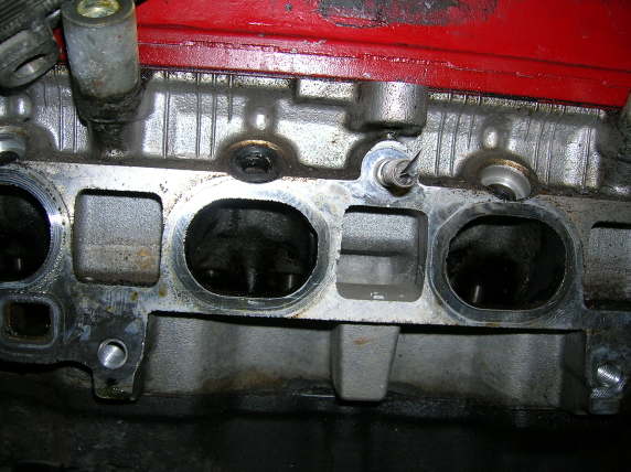
STEP 4 - Removing the old intake manifold
There are 3 nuts along the top of the flange, and 3 bolts along the bottom of the flange. All 6 fasteners are 12mm. A ratchet may be used to unbolt the top 3 nuts, but you will need a 12mm wrench to undo the bottom 3 bolts. This is where those ratcher wrenches are a godsend.
STEP 5 - Cleaning the head and preparing to install the new ACIS manifold
Make sure you clean off all of the old gasket residue off of the head and the new manifold.

Some alterations will have to be made to the coolant line. They need to be bent outward towards the drivers side.
Circle #1 and Circle #2 are the areas to bend outward... be careful here and don't reef on it. We move this cooland line out of the way because the ACIS Manifold is quite a bit larger, and therefore needs more clearance.
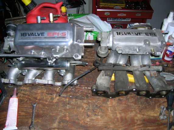
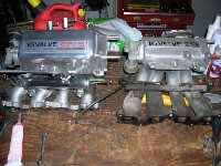
ACIS MANIFOLD to STANDARD MANIFOLD COMPARISON
STEP 6 - Installing the ACIS manifold
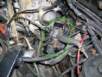
This manifold bolts up exactly to the existing mounts. The only difference is that none of the support mounts will bolt up. This is where you use your imagination and fabricate something!!
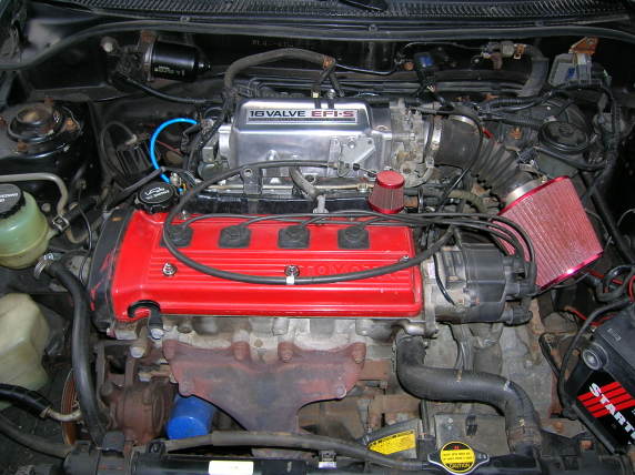
Notice the CHARCOAL CANISTER circled in green. You will have to move it down. I've simply taken it off of the mount (slide the canister down) and let it hang/rest on the other vacuum lines. No harm in that, but I will eventually make a mount for it.
STEP 7 - Installing the throttle body
Put the gasket on or just seal it using gasket maker. No harm there because it's only air. Bolt it up using the 2 nuts and the 2 bolts.
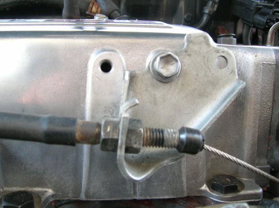
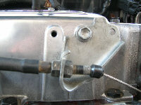
STEP 8 - Attaching the throttle cable.
Notice I had to offset the bracket by 1 hole. The stock 5E-FE cable is just a little short, so I had to compensate by moving the bracket down. That bracket is also the stock 5E-FE bracket, I just unbolted it from the old Manifold.
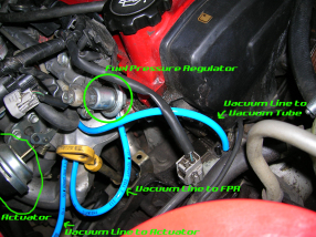
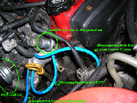
STEP 9 - Attaching the vacuum lines
Here's where it might get a little confusing..
This picture mostly explains the MAIN vacuum lines. The vacuum diagram is virtually IDENTICAL to the 5E-FE. However, the extra line is the line from the manifold to the actuator.
Some downsides...
Now because the actuator is hooked into the manifold, the actuator ONLY opens if you gun it. Thats when the pressure in the manifold is high enough to open the secondaries. In order to properly make this work, stick a check valve in that line, and that allows you to regulate at what pressure (or rpms) the actuator will open. This is the way i have it rigged right now.
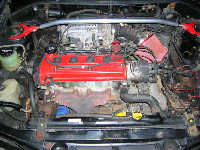
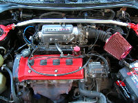
And of course, here is the finished product!

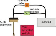
Here is some additional information collected by Paseo92 on activating the secondary runners without a 5E-FHE ECU.
I've been mulling over ways to activate the ACIS since the stock ecu has no provision for this. I don't want to just hook it up to manifold vacuum because it'll open at WOT regardless of rpm and from what I can gather 3800 rpm is the magic number. Testing still needs to be done to confirm this though. A simple vacuum gauge hooked up to the right parts of the manifold will give you this information. I think I have something that will work. I'll try to describe it as best as possible, so here goes.
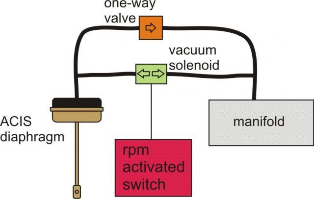
First run a vacuum line from the manifold to a "normally closed" vacuum solenoid valve. These can be found on almost any import for a couple of bucks at the junkyard. Then run a line from the solenoid to the ACIS diaphragm. Use a RPM activated switch (such a unit is made by MSD) set to 3800 to trigger the solenoid. MSD says their switch will work with the stock ignition system.
To ensure that vacuum is available to shut the ACIS in the event rpm drops below 3800 thereby causing the solenoid to close before vacuum is sufficient to shut the runners a tee can be inserted on each side of the solenoid and a bypass used with a one-way vacuum valve. This would also prevent ACIS operation at light throttle cruise at or above the set rpm but the instant you hammer the throttle and vacuum drops then the ACIS will open.
BACK