Here I will document the progress made on the 3E-ZE. Everything will be listed in reverse order so the newest news is always at the top.
11/11/07
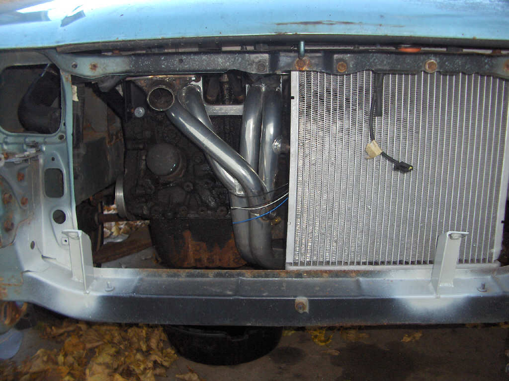
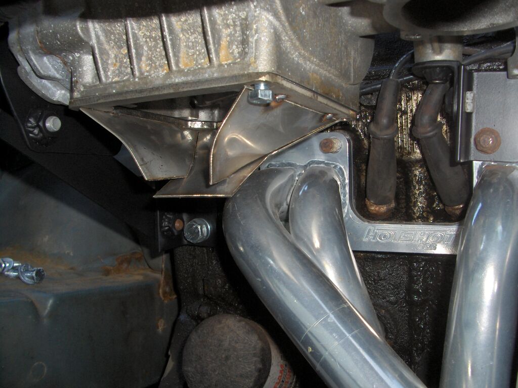
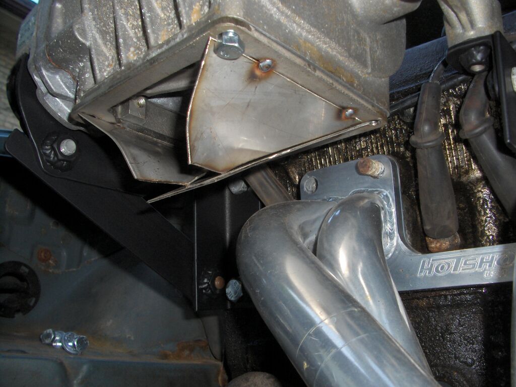
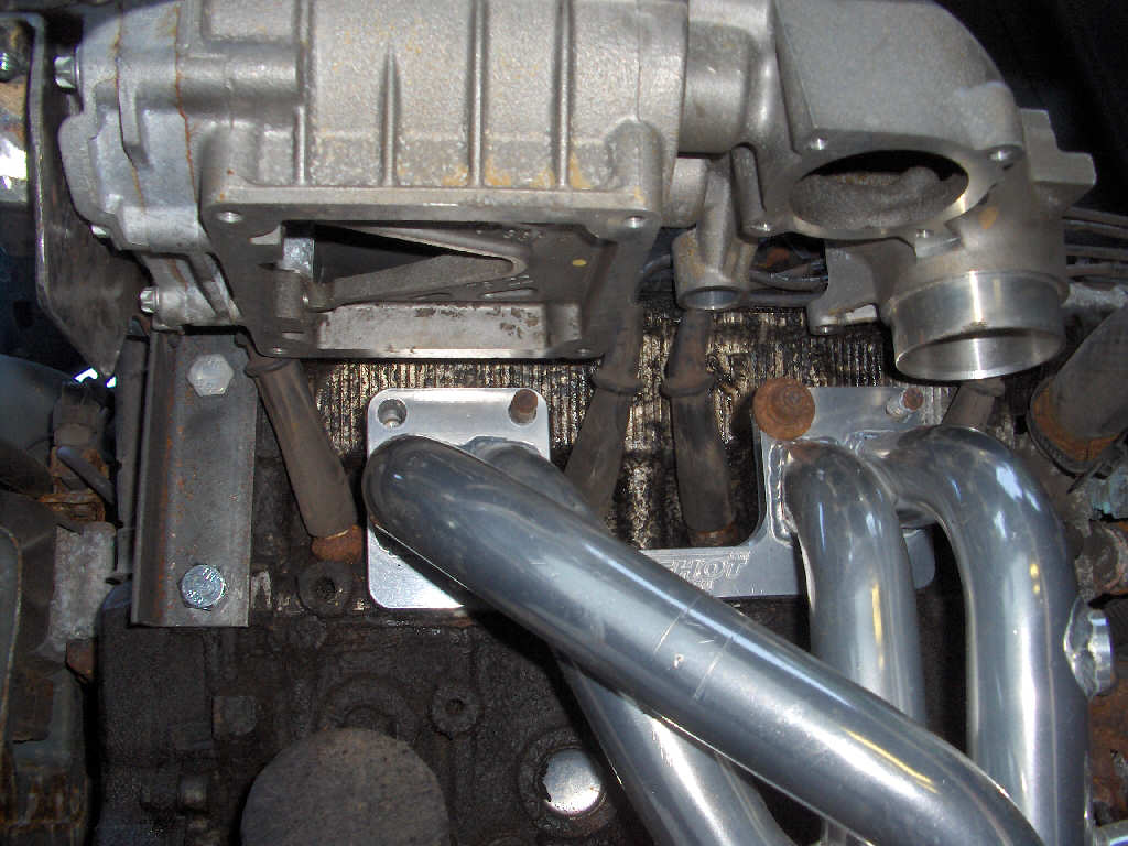
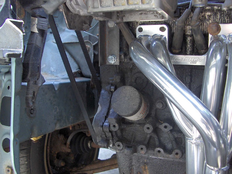
There has been a bunch more work done since the last update. There was a problem with the header. It was hitting the oil pan as it curved to go under the engine. So, not wanting to alter the header, I took a pneumatic hammer and reshapped the oil pan a little bit. It worked like a charm and there is now a nice 1/8" or so of clearance.
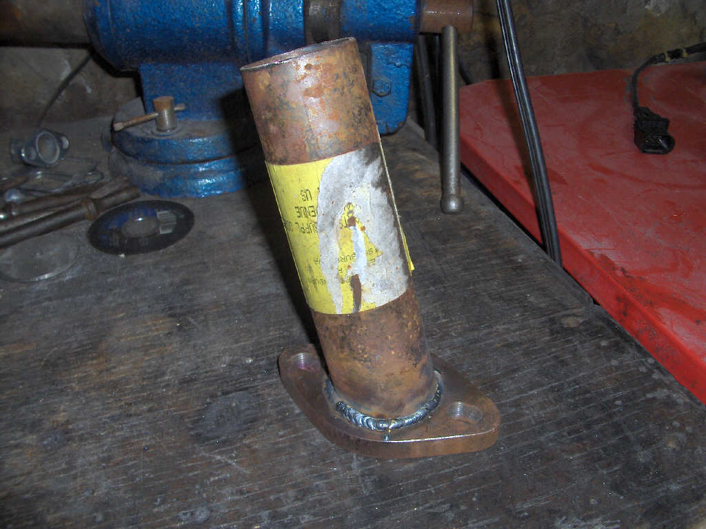
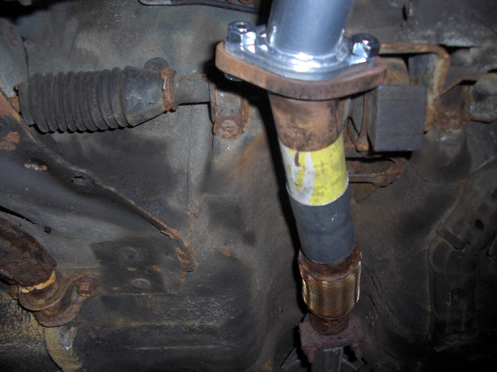
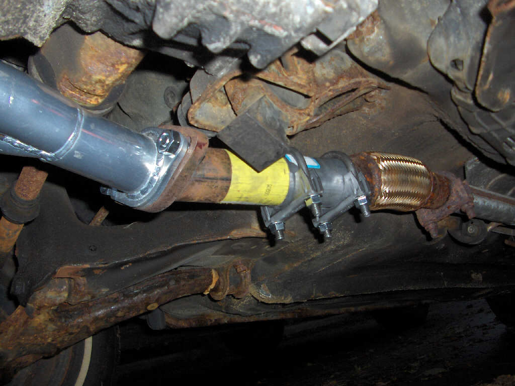
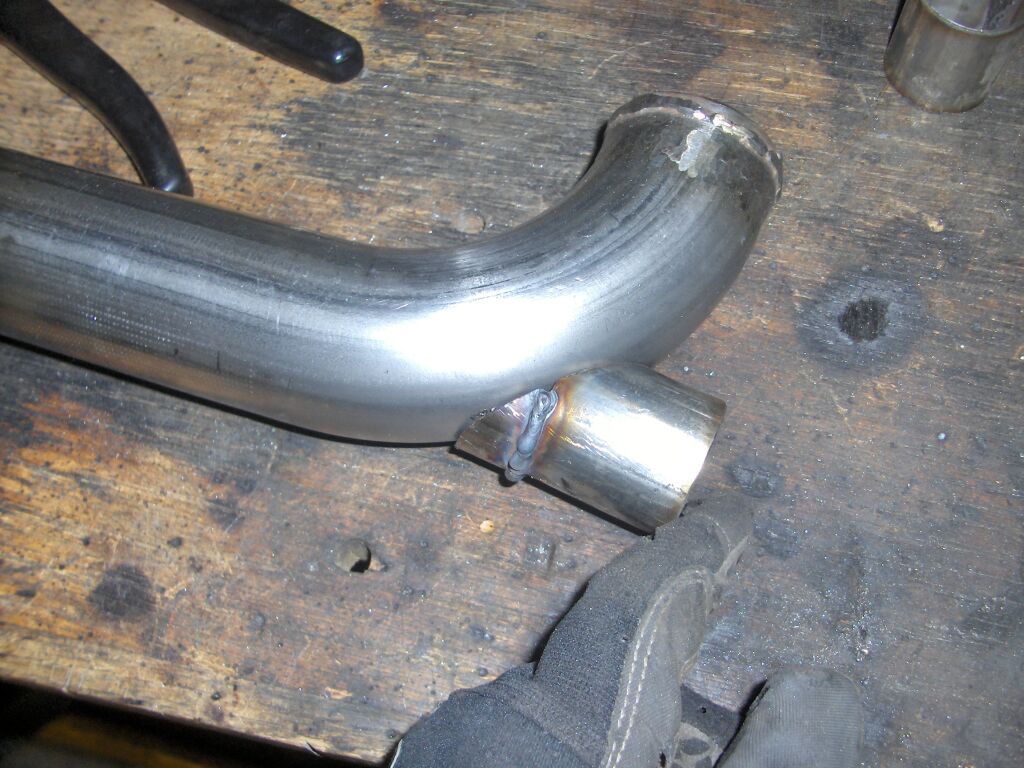
After the header was able to be mounted properly, I had to make a piece that fit between it and the existing exhaust. It is an ugly piece, but the rest of the exhaust will be replaced come summer time and I wasn't going to waste good mandrel bends for that short amount of time. The piece worked great and mounted up very well.
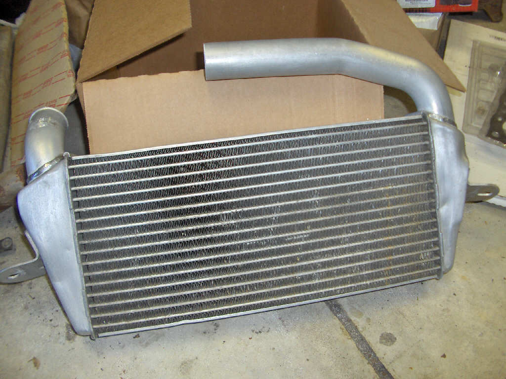
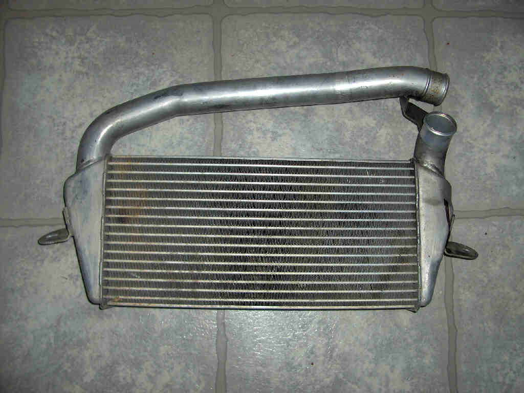
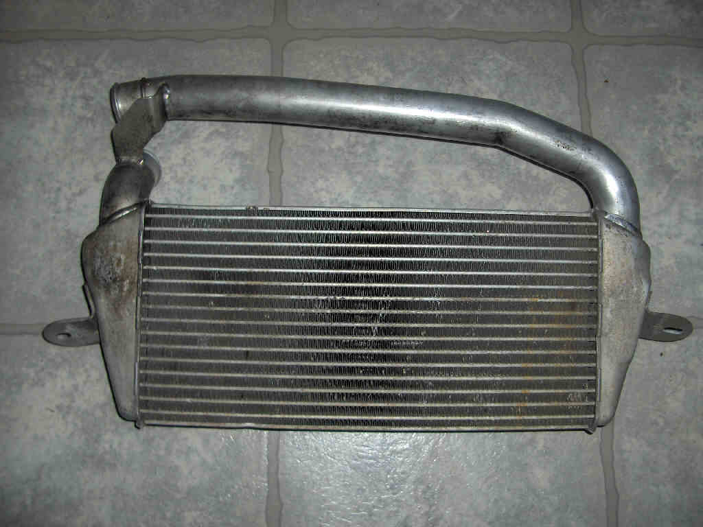
While I was doing all that other stuff I had my intercooler sitting in my parts washer to get cleaned out. I had noticed a little bit of oil in it when I got it, and there were some metal shavings in it from cutting it so it had to be cleaned out. After taking it out of the parts washer and rinsing it out I took some scotch brite to it to shine it up a bit too. Doesn't look too bad if you ask me.
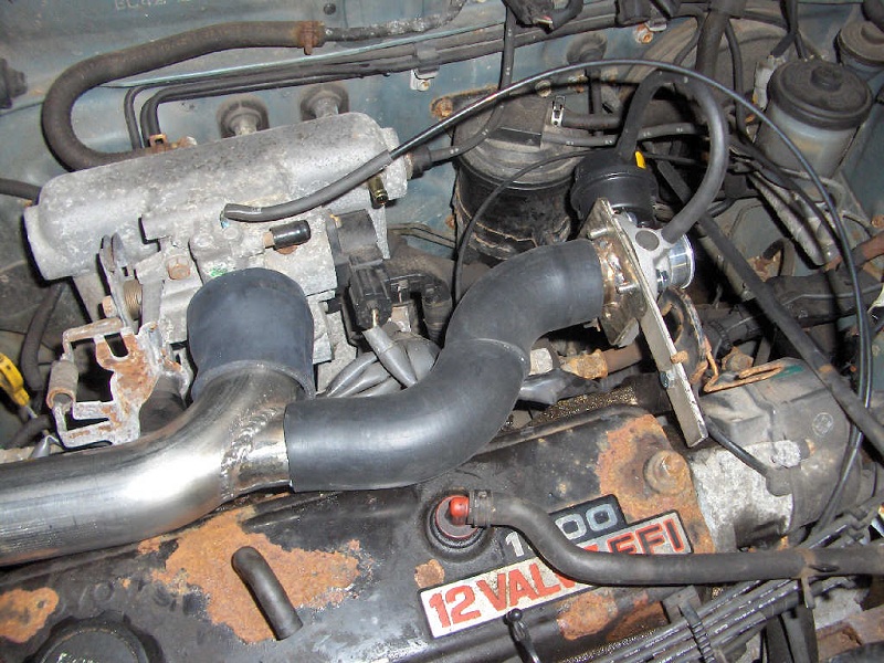
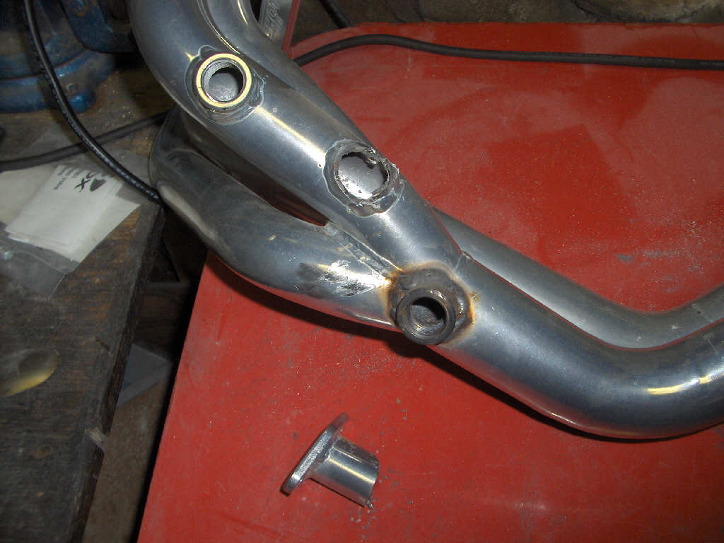
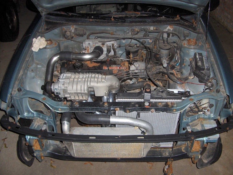
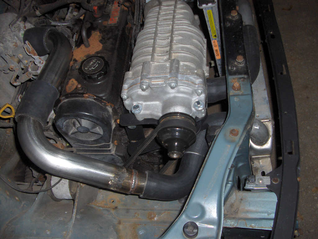
With the exhaust hooked up and the intercooler cleaned, it is finally time to put everything back on to the car! Reassembly went great until I found out that the oxygen sensor comming off one of the header ports points straight at the radiator fan and actually protrudes far enough that it'll hit the blade if it spins. So, I had to go and remount the radiator fan to the side. I'm still not sure if I'll keep the stock fan or go with some other fan, but its fixed for the time being.
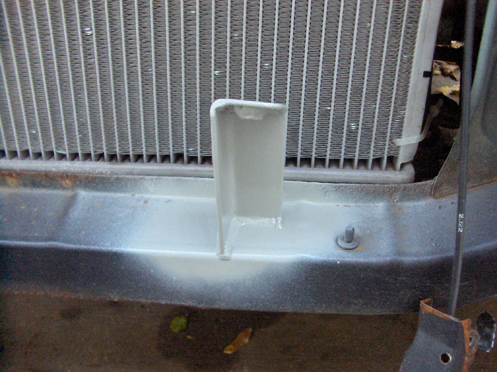
So, continuing on with the reassembly I remembered I'd need a way to bolt the intercooler to the frame. So, a bit of cutting and welding later I had intercooler mounts made up and welded to the car.
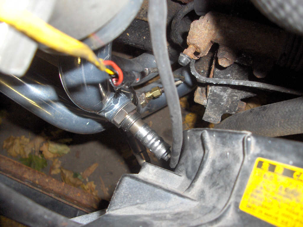
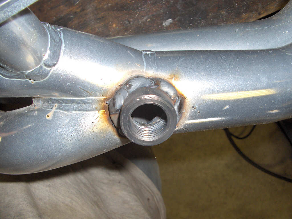
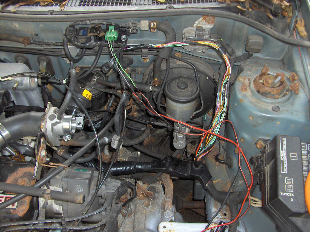
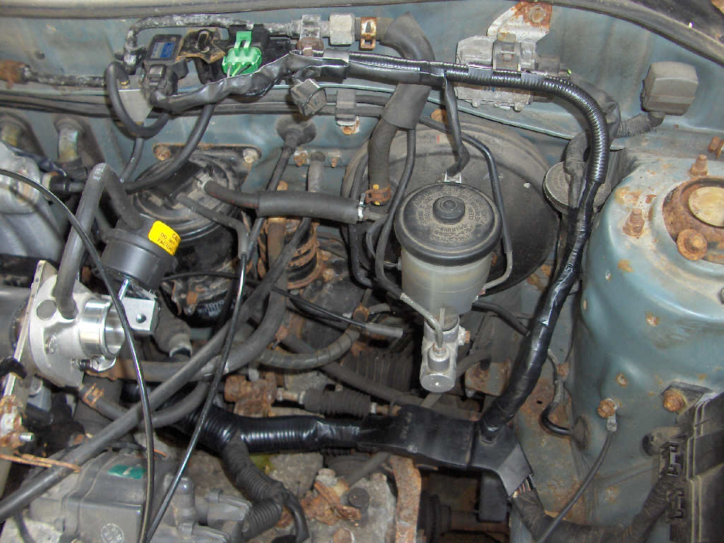
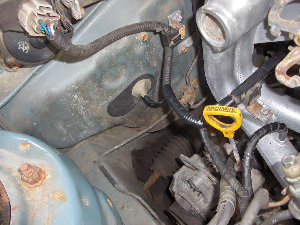
The next step was to plug in all the sensors that go into the exhaust. I had to order a new oxygen sensor for the car since stock sensor is a flange mount type and the header has a screw in port on it. Wired that up and installed it. I also put in the Innovate wideband oxygen sensor and the EGT probe. It kind of made a mess of the engine bay, and it still needs to be cleaned up.
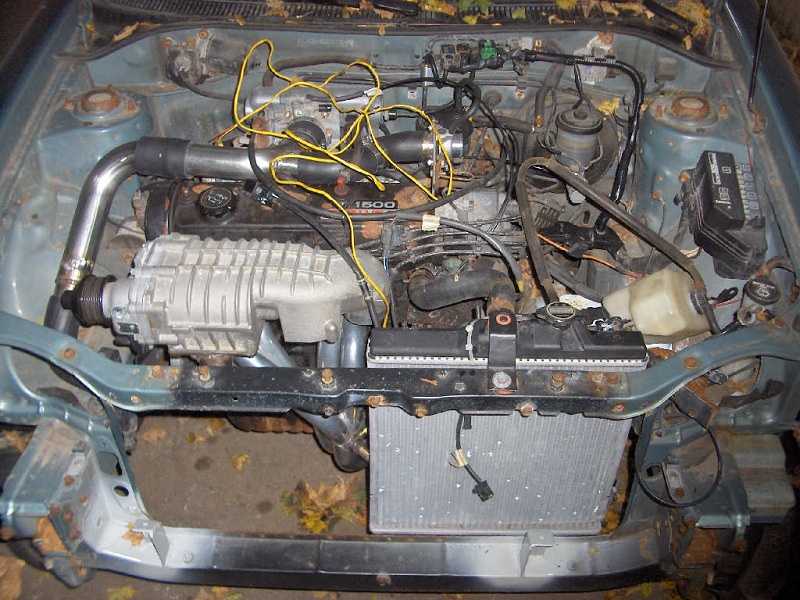
Now that all the exhaust ports are plugged up with sensors it was finally time to give it a try and fire it up. Keep in mind that the supercharger belt is not attached yet. So, I got the laptop out and configured the E-manage for the first time. Then, I turned the key to the happy sound of a rough idle. It quickly smoothed out and purred nice and smooth! Feels great to have it fire up on the first try. I ended up moving the car into the garage and that is where this tale ends for today. I'm very glad I got the car inside before the first snowfall.
10/9/07
There is a light at the end of the tunnel after all. This are starting to all come together. I've been putting a lot of time into the car lately so it is up and running before winter.
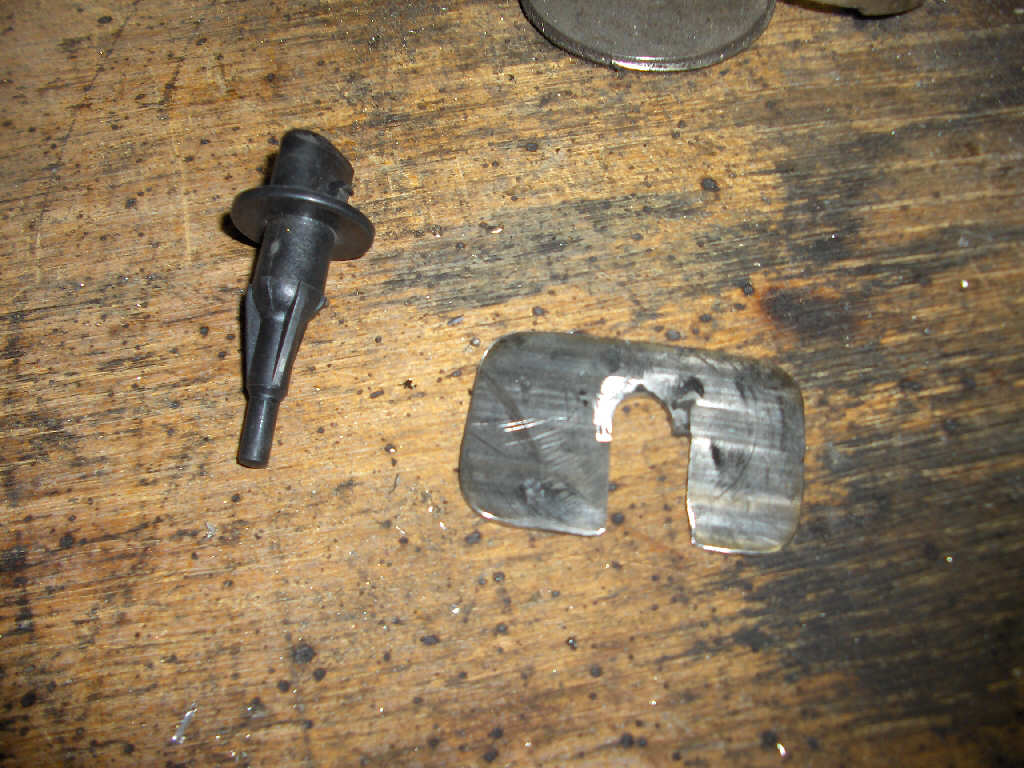
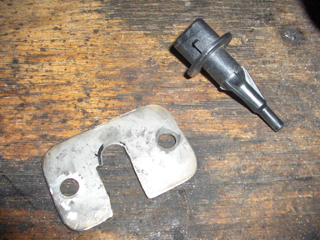
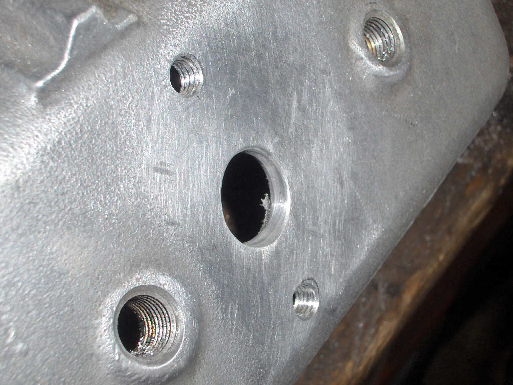
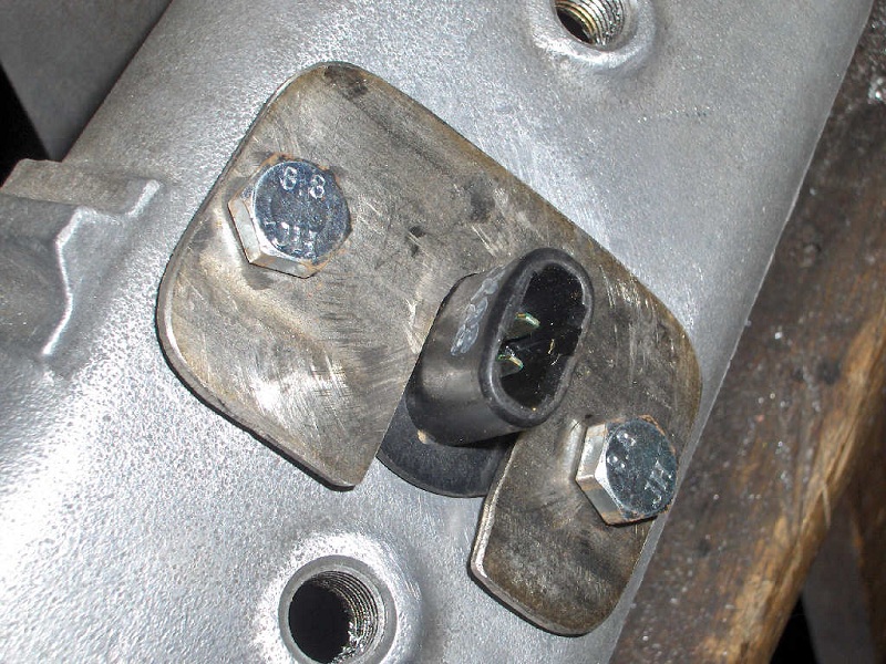
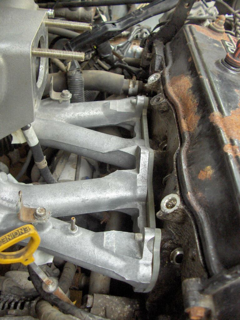
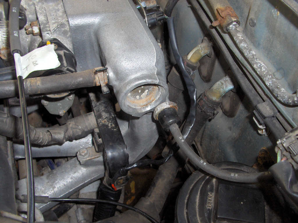
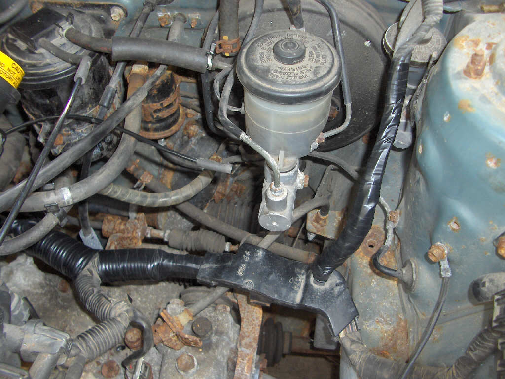
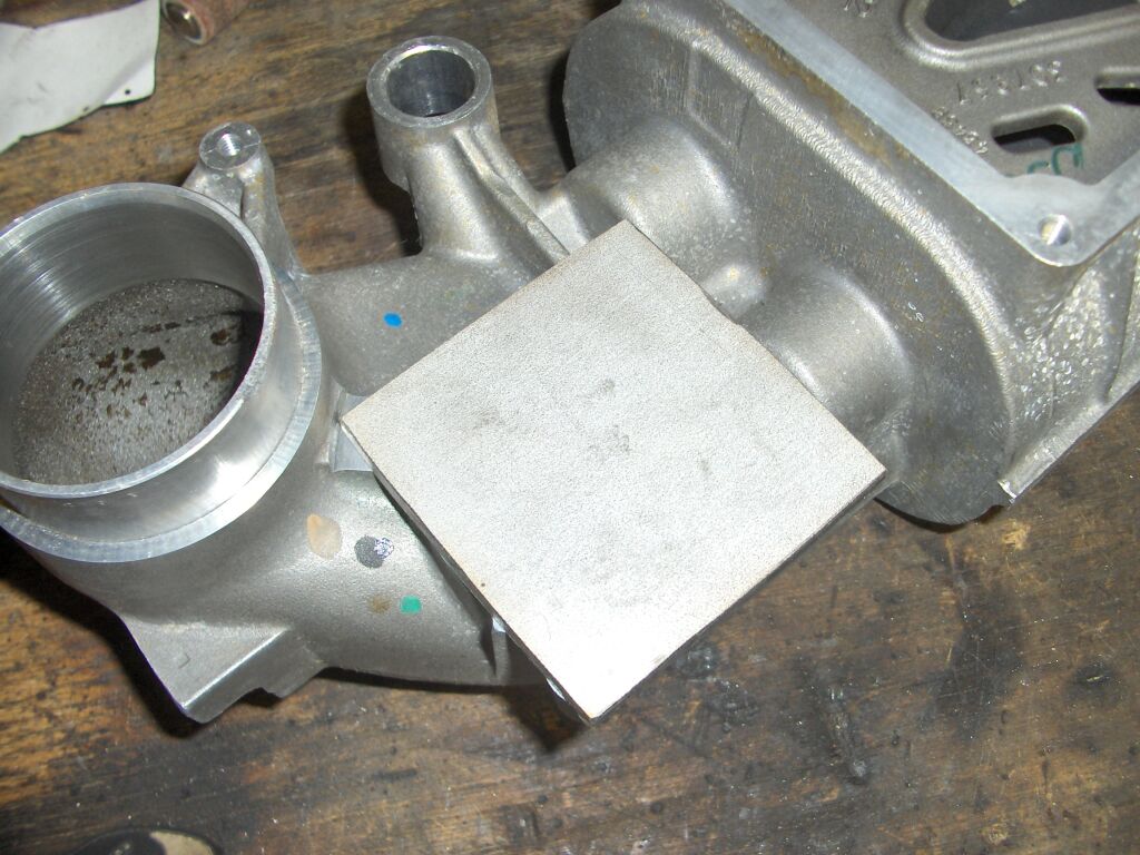
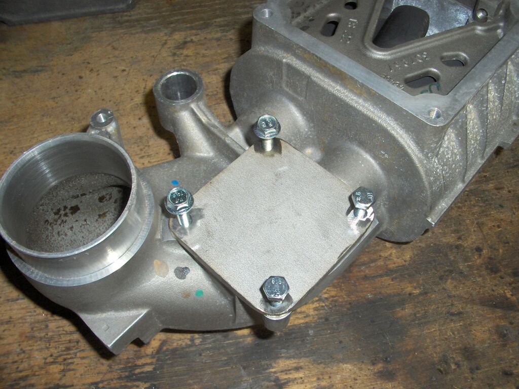
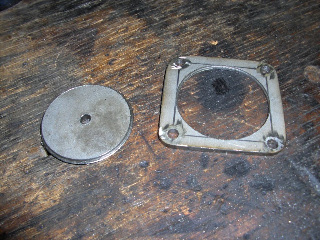
First off I had to make yet another flange. This one is for the intake air temperature sensore. This flange holds the sensor in the intake manifold when there is boost pressure so it doesn't get blown out of its hole. I also had to modify a spare intake manifold so I could mount the sensor to it.
Back to the intake plumbing again. I mounted the bypass valve and ran a line to it.
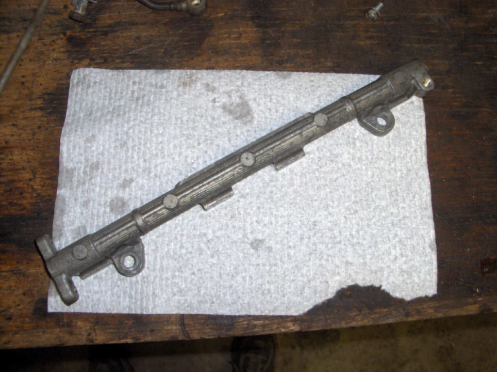
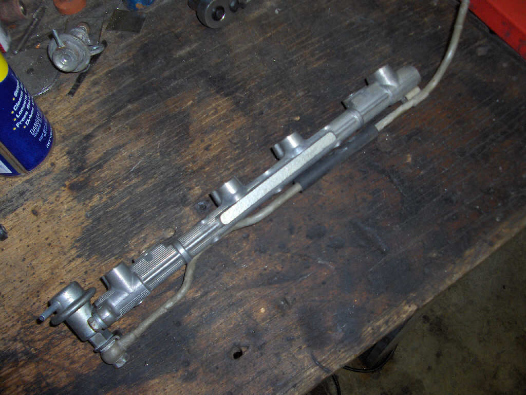
After that it was time to work on the fuel system. First on the list was to take apart an extra fuel rail I had. I cleaned it up, and replaced the 3E-E fuel pressure regulator with a 4E-FTE pressure regulator that compensates fuel pressure when there is boost.
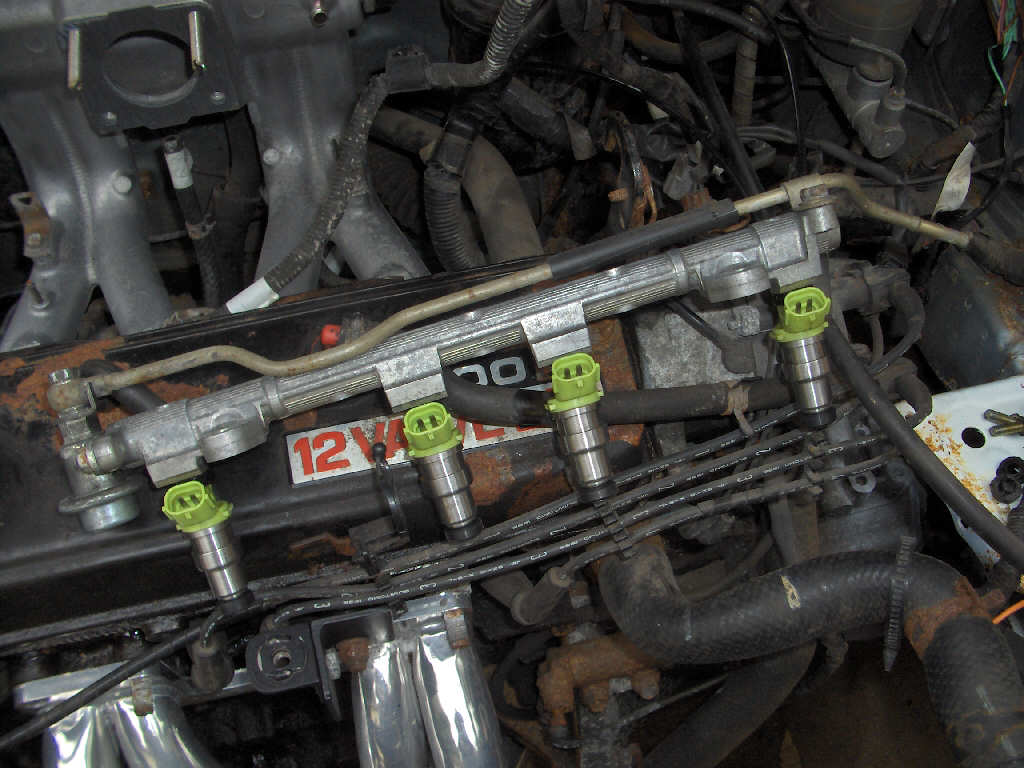
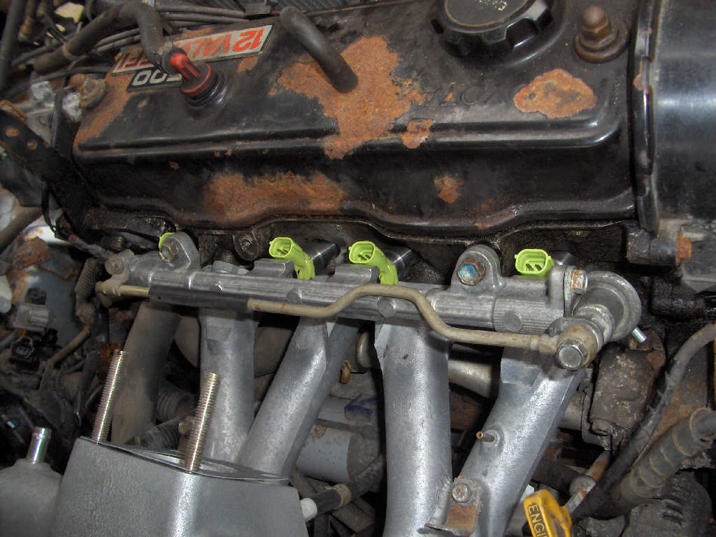
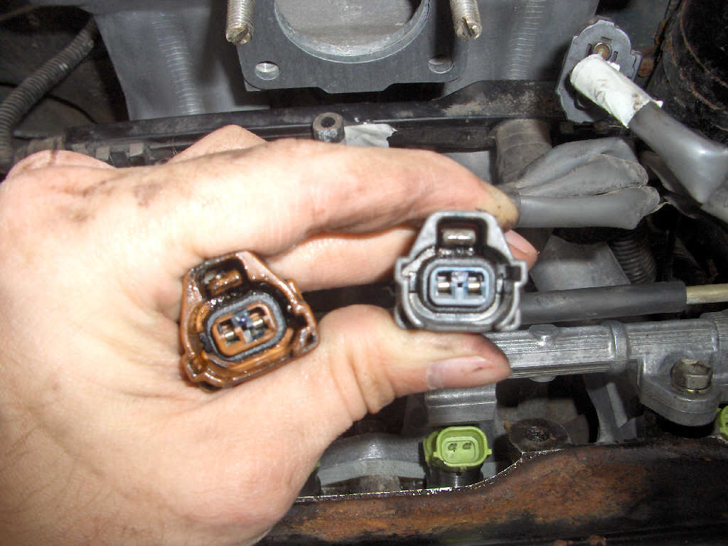
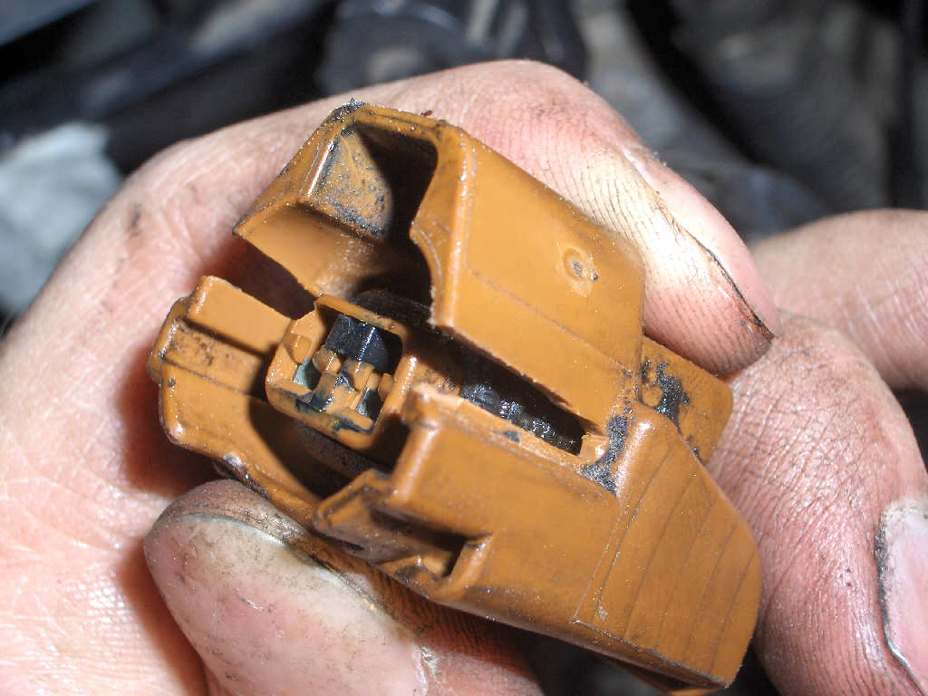
Now, back to working on the car. This time around I ripped out all the intake plumbing, throttle body, intake manifold, and fuel rail. The new intake manifold and fuel rail went back in (with the shiny new Supra injectors). Then the throttle body and intake plumbing went back on. I had a little hickup with the injector connectors. Since there are two different injectors on a stock 3E-E there are also two different connectors. Thankfully, I found a quick fix by adding a slot to them. I'll most likely pick up a spare set of connectors and wire them in properly.
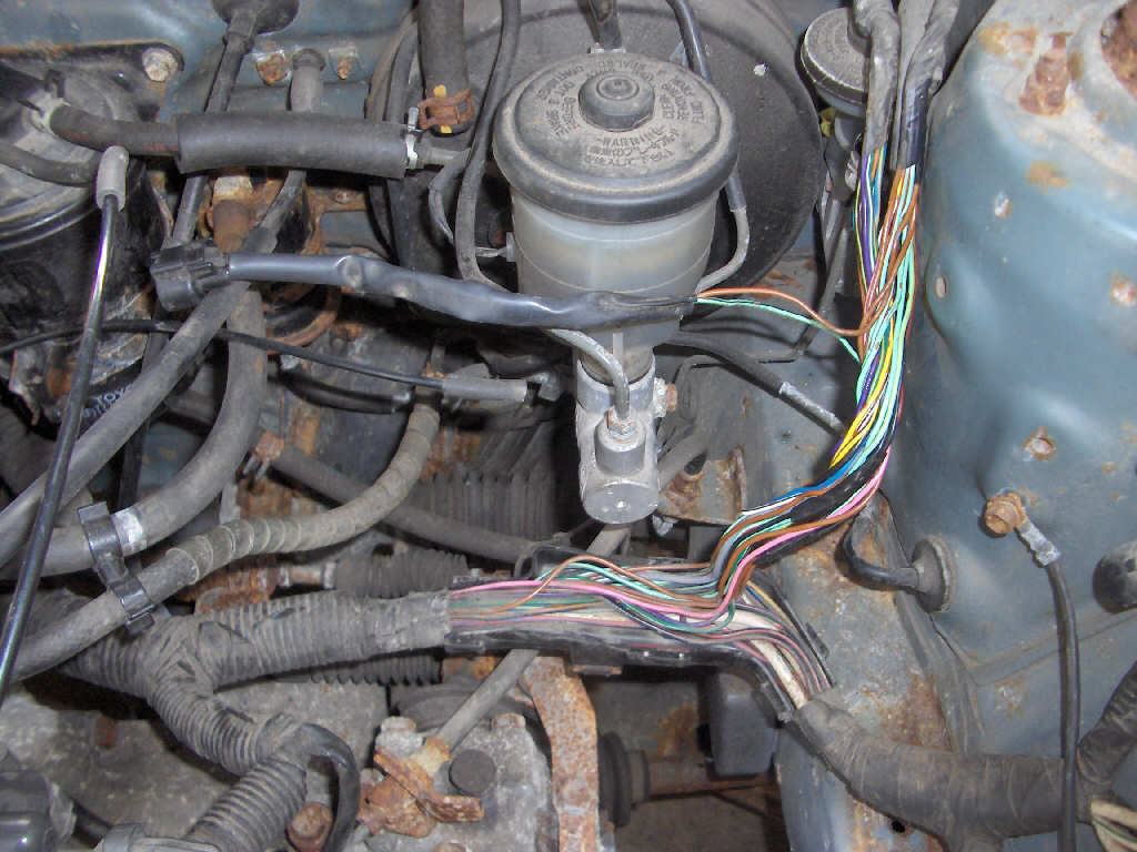
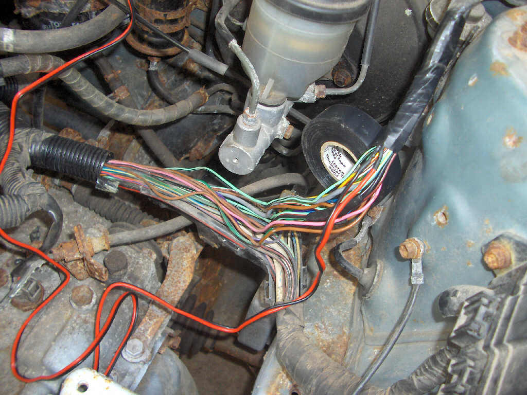
Now, on to the electrical side for a while. With the intake air temperature sensor mounted in the manifold, the wires were not long enough for the connector to reach the sensor. So, I had to cut the wires and run an extension to the new location. Wanting everything to be as clean as possible made this take some time as I had to unwrap a lot of wiring. However, you can't even tell it had to be done now, and I like that.
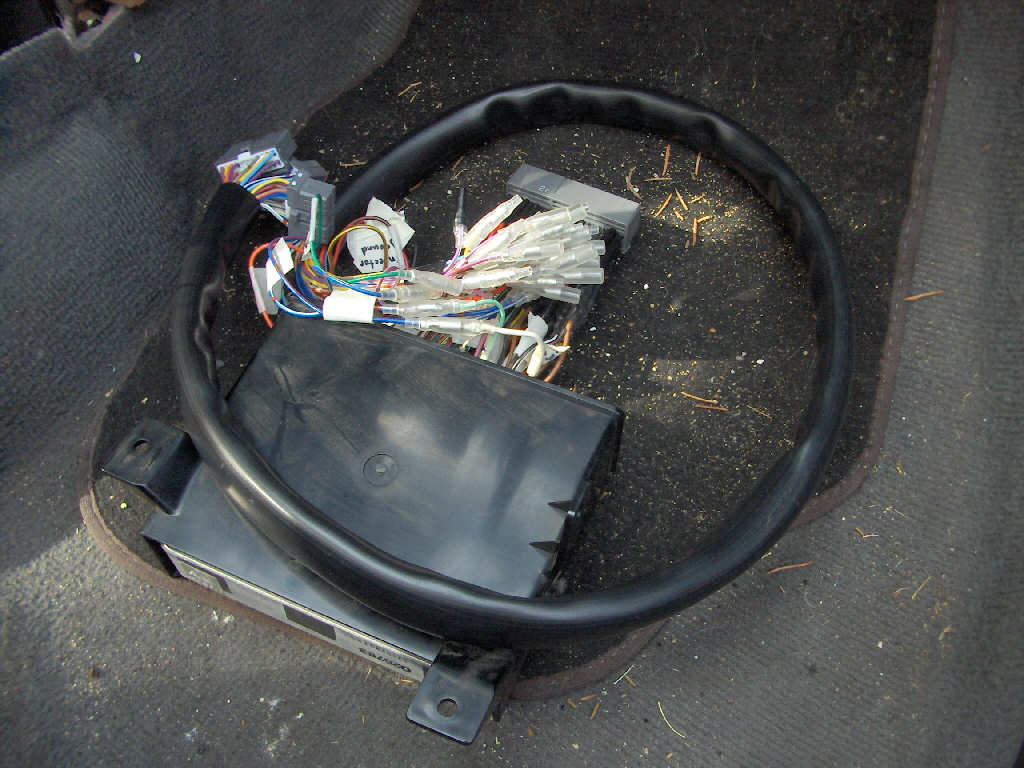
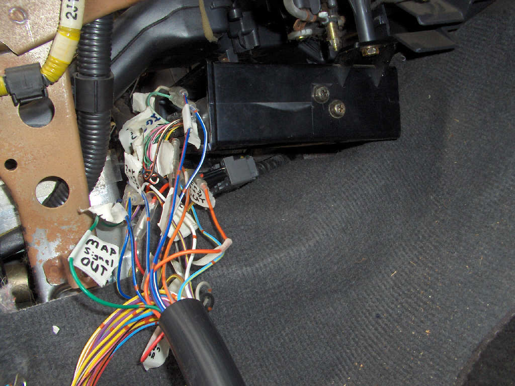
Continuing on with the electrical side of things I went and reinstalled the ECU I had taken out a few weeks back. The ECU was put in with the newly made E-manage plug and play harness I had made. The fit was quite tight, but it fit after rearranging some wires.
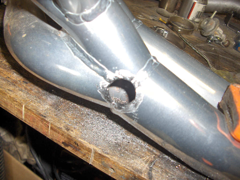
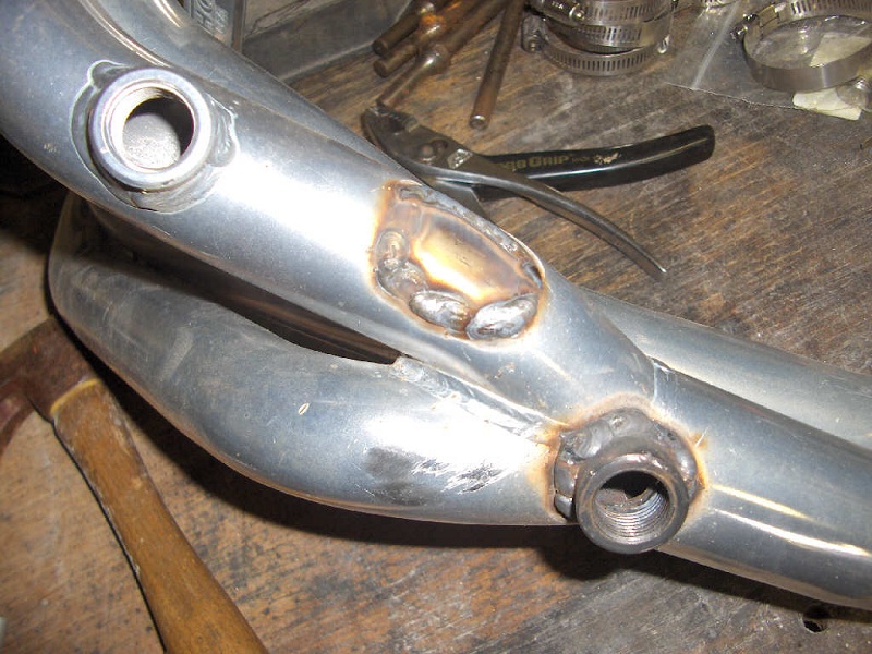
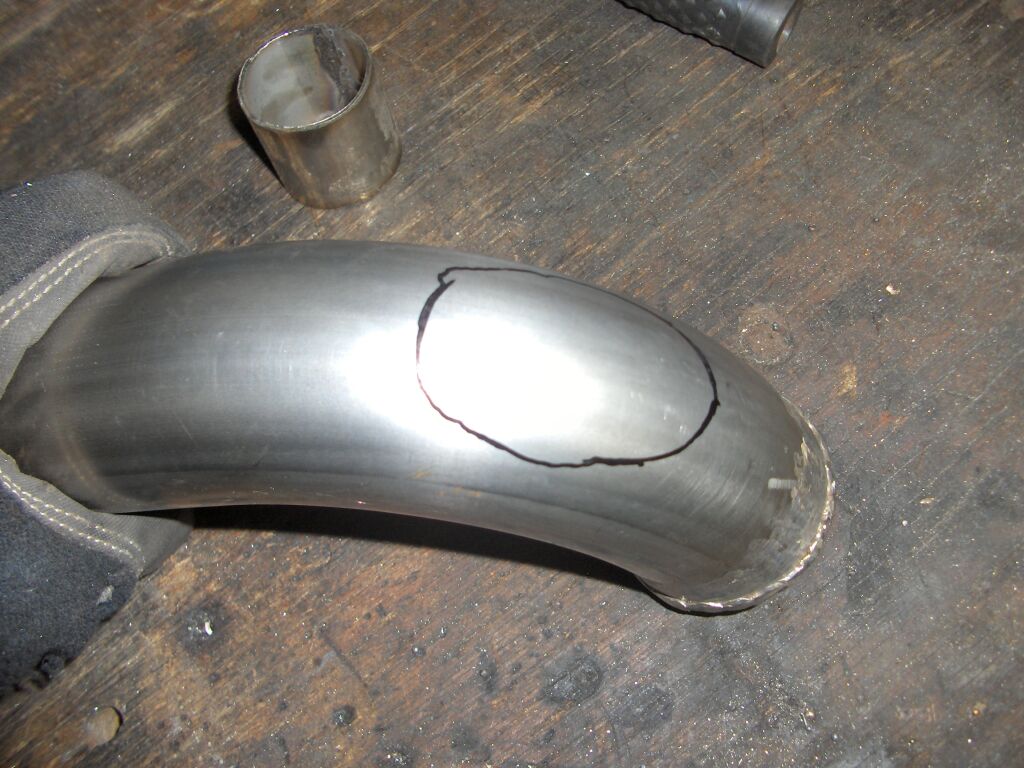
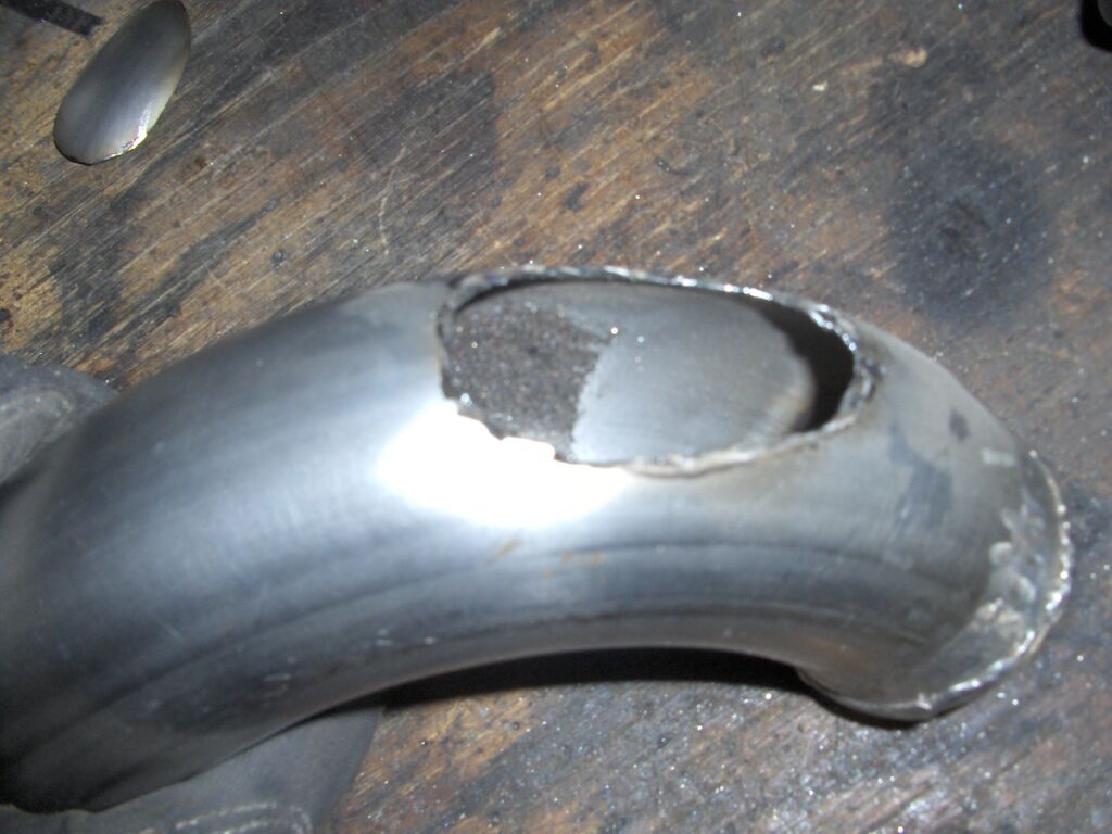
Next on the list was modifications to the exhaust. I needed to add another oxygen sensor hole for the Innovate LC-1's oxygen sensor to mount in. This was pretty easy. I just drill a hole and welded the bung on that came with the Innovate kit. Finally, I chopped off and welded over the flanged oxygen sensor mount as it won't be used.
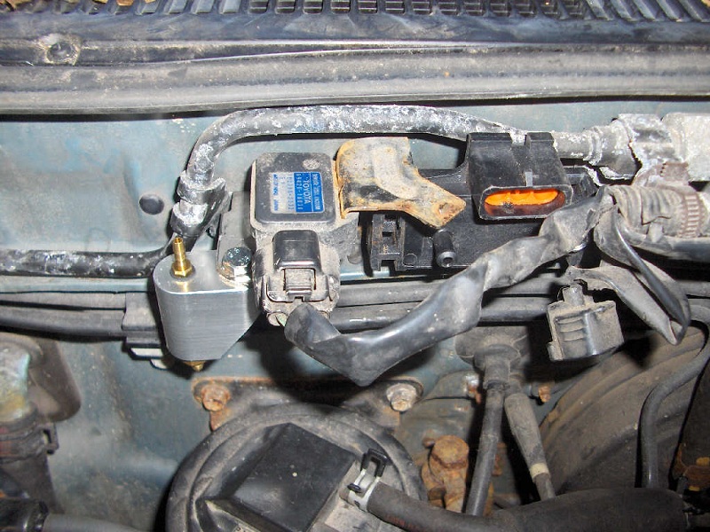
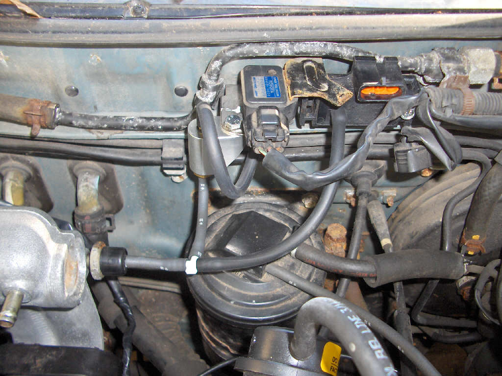
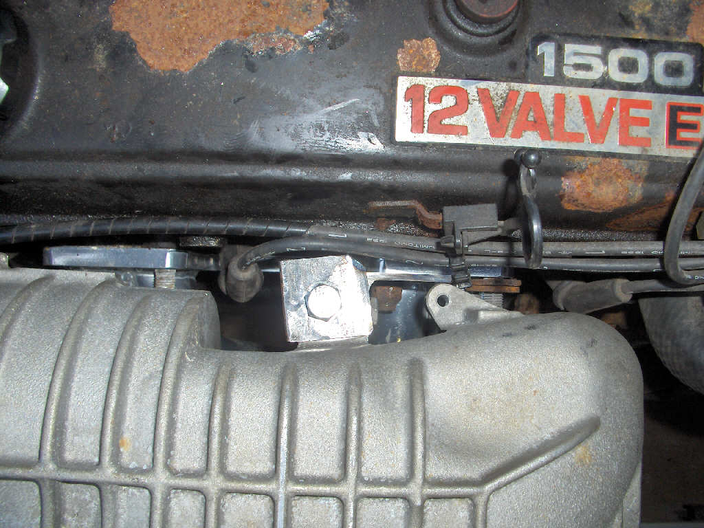
As the sun started to wind down for the weekend, I took a bit of time to mount the GM MAP sensor for the E-manage and my missing link check valve. I managed to fit them nice and close together so I don't have to run vacuum lines all over the place which keeps it nice and tidy. I also ran the wiring for the MAP sensor.
9/14/07
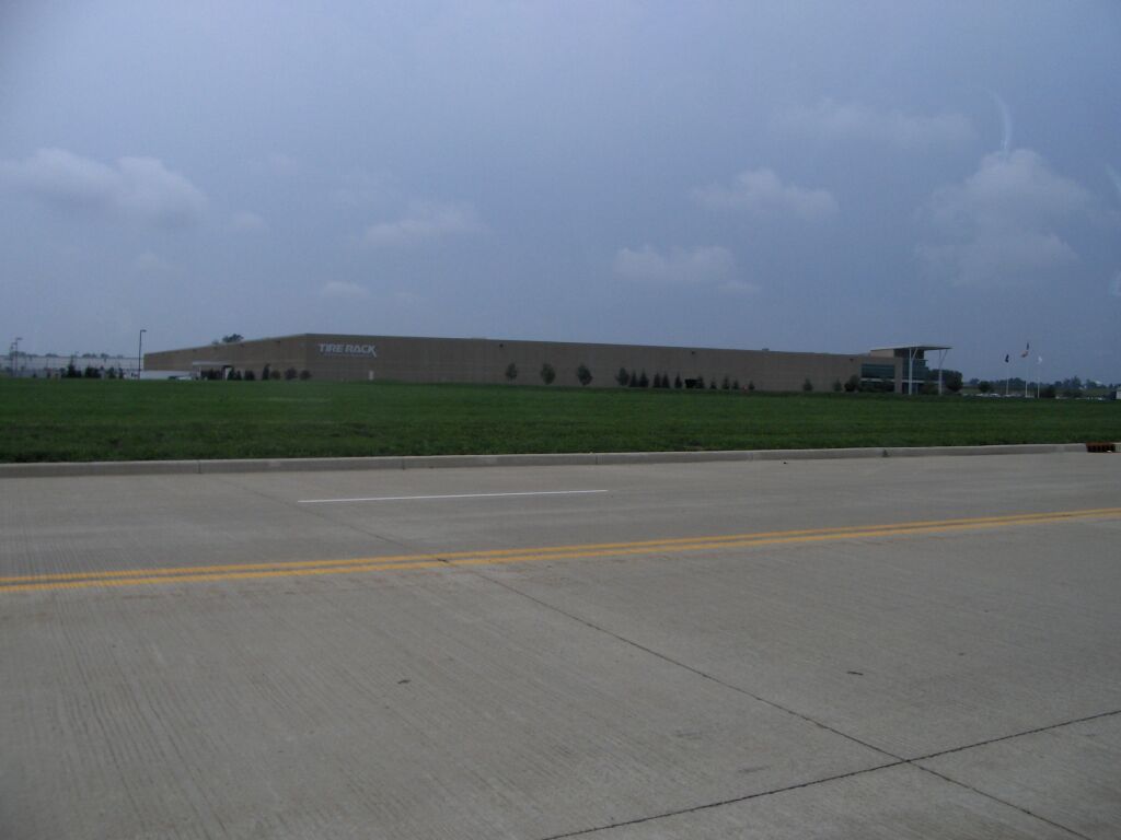
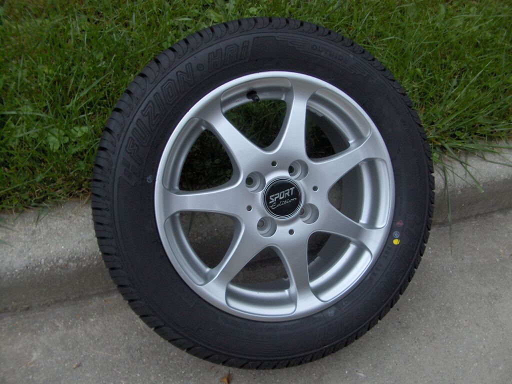
Slowly but surely its still comming together. I've been gone a lot since the last update. But, I've taken every chance I've had to work on the car to get it running as soon as possible. While I was away on a trip to the Detroit area I decided to stop by Tire Rack and save myself a hefty $75 on shipping by picking up my wheel and tire set that I had picked out from their website. The place was simply gigantic as you can see below. Oh, the wheels look good too!
Between all the trips I got to do some more work on the intake plumbing. First off was a flange for the supercharger intake. For it I used the same stainless that I made the supercharger outlet flange out of. It worked pretty well.
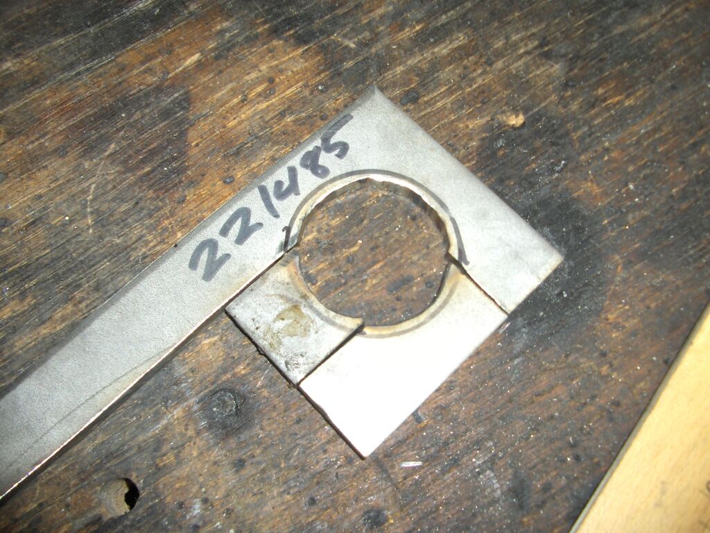
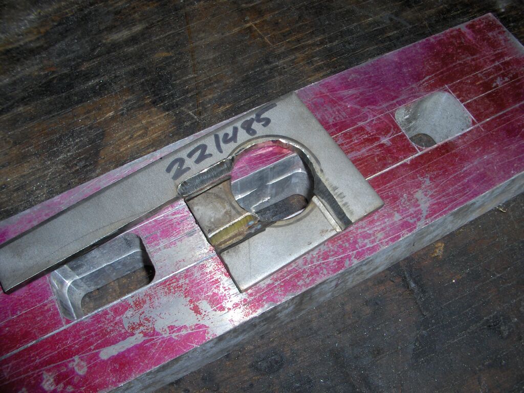
After the intake flange was finished I needed to make a flange for the bypass valve to mount to. I had originally wanted this bolted directly to the intake plumbing similar to how a blow off valve would be mounted. However, I couldn't find sufficient room to mount it where I wanted, so it will be mounted remotely. I also ran out of stainless steel to make the flange from a solid piece. So, I had to improvise and use what was left from making the other flanges. It still needs to be cleaned up a little, but it came out very flat and shouldn't have any problem sealing as I'll be using a 1/16" thick gasket. Also, since I didn't have any 1.5" diameter tubing I made the short tube out of 2" tubing cut down and welded together.
Next, I took care of the other end of what the bypass flange will connect to, the intake piping. This went quite smoothly and also came out very well. This intake pipe is the one that goes to the throttle body. Sorry for the blurry pictures, I don't know why the camera was acting up.
8/14/07
Finally making good headway on this project. I've been putting in as many hours into it as I can. Thus, we have another updated to speak of. I ran out of things to powder coat, so I moved on to other things I could do indoors while weather didn't permit working on the car outside. So, I wired the E-manage harness to the plug and play harness that I made a while back.
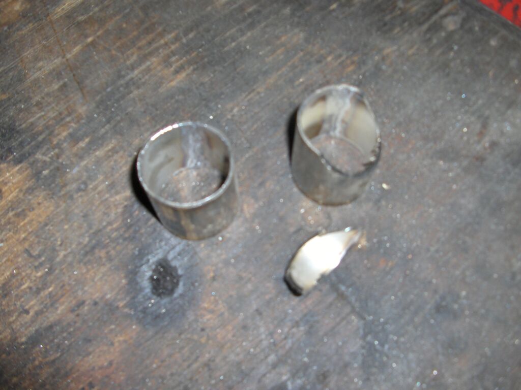
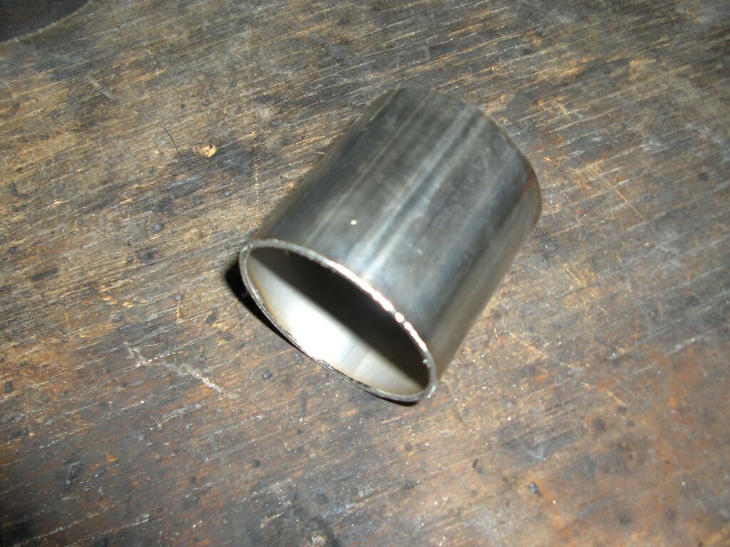
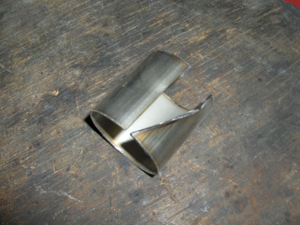
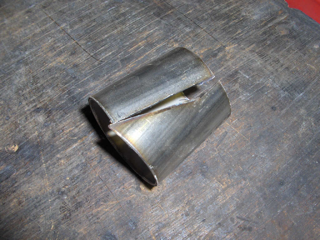
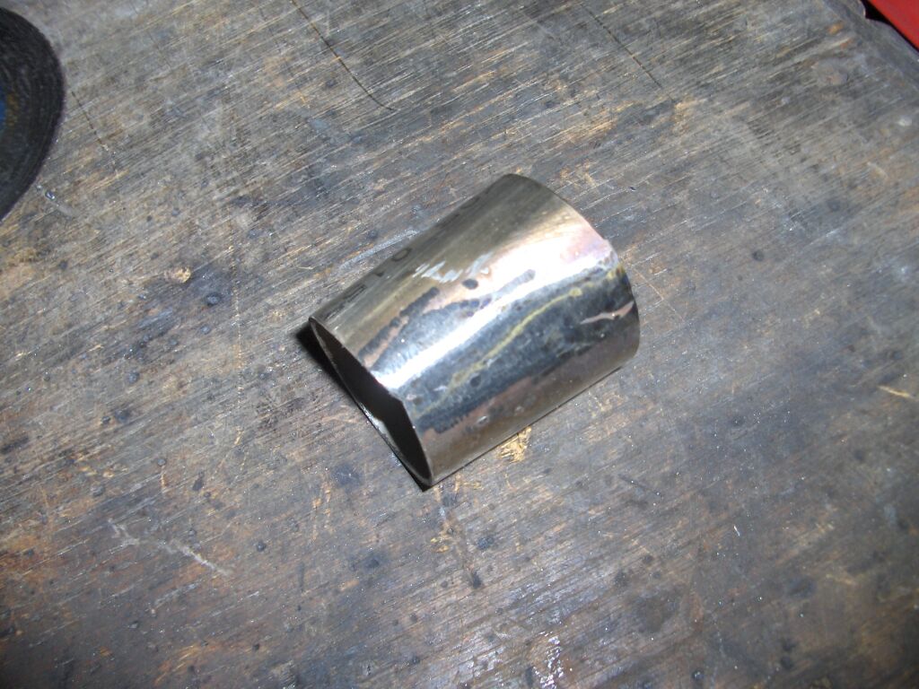
I'm still working on the intake plumbing. Since the intercooler piping is 1.75" and I am using 2" pipe for the rest of the system I needed to make two tapered adapters. I was wondering where I could get these then realized... Hey, I could just make them, duh! So, I did make them. It was very simple actually, and didn't take much time at all. I'd explain how I went about it, but the pictures are pretty self explanitory.
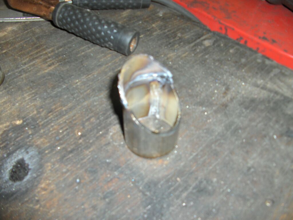
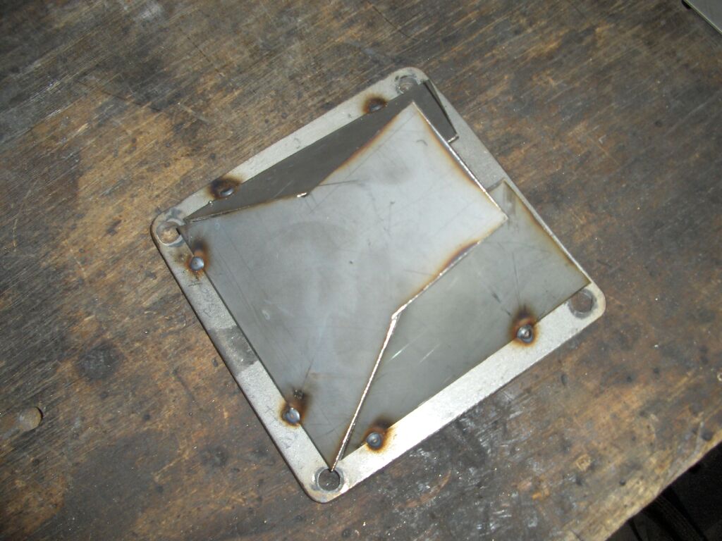
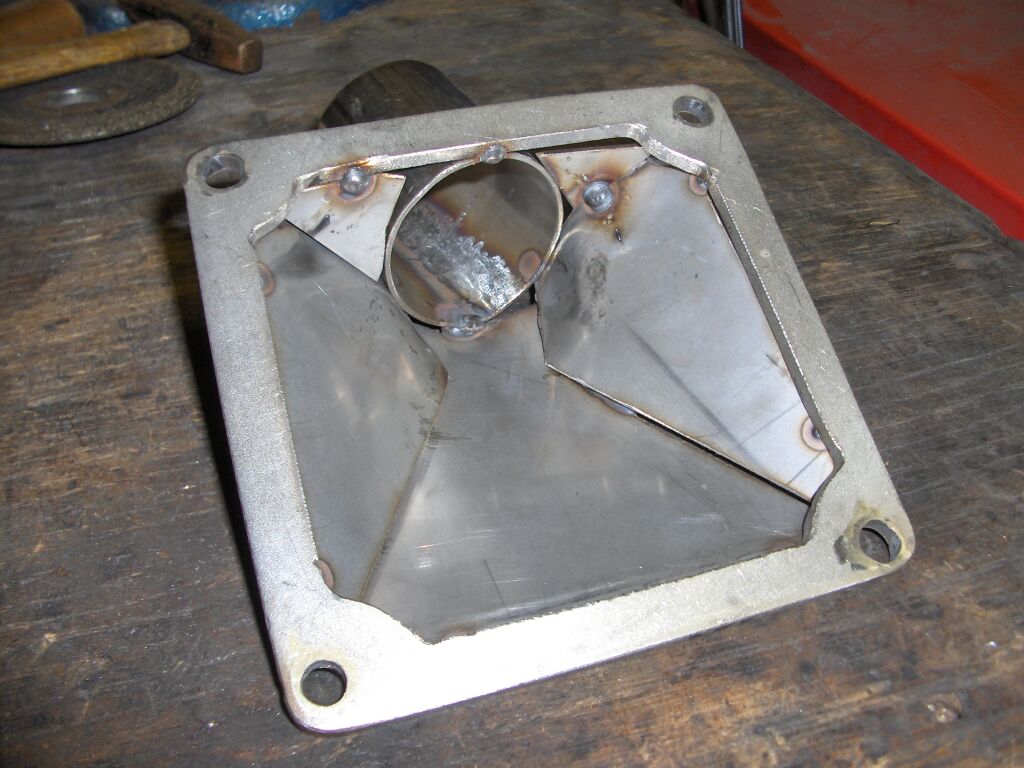
I took the other night to make up the supercharger outlet collector. It actually went very smooth and came together nicely. The welding doesn't look amazing, but its air tight and it'll work well. Just as a side note the stainless steel wasn't too difficult to weld. It did take a good bit of playing around with the welder settings though.
I pieced together the rest of the intake plumbing from the supercharger to the throttle body. It fits great. I will have to make some brackets to hold it in place though. With that done I can finally make the mounts for the intercooler.
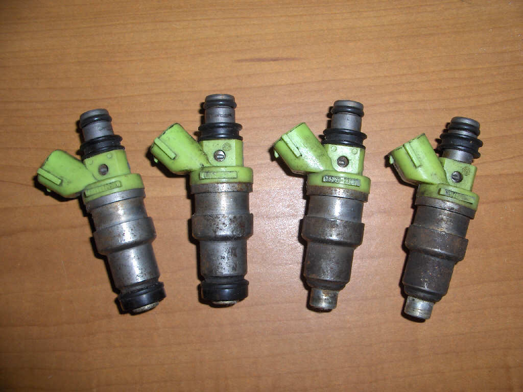
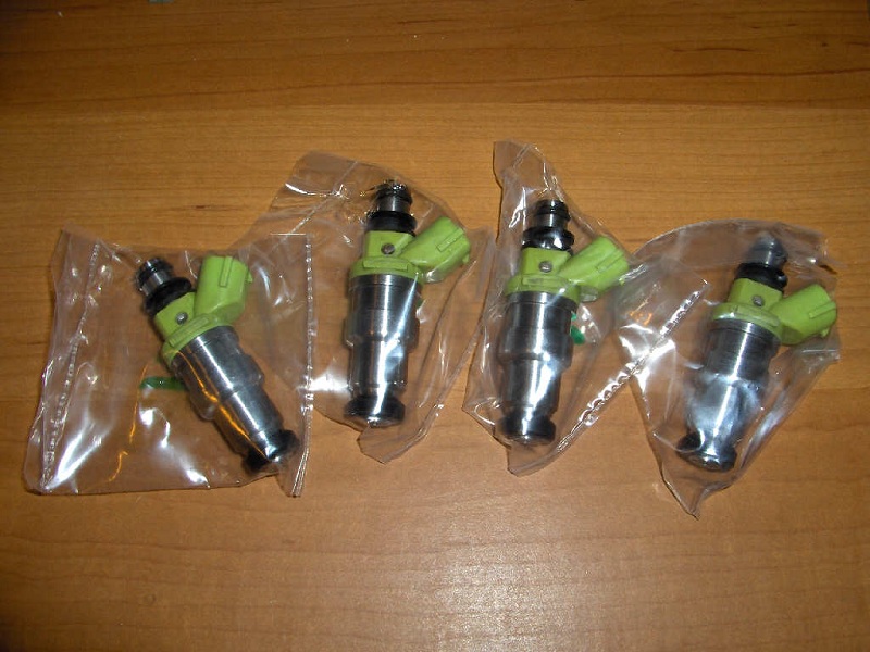
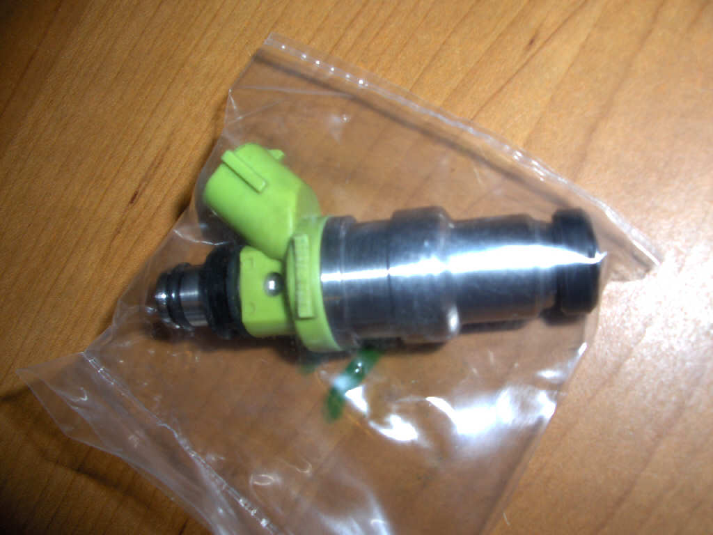
Last, but not least are my newly cleaned and flow tested Toyota Supra 7M-GE 315cc/minute fuel injectors. I just got them back from Cruzin Performance. We have a before picture on the left and two after pictures on the right.
8/7/07
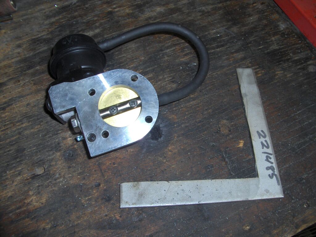
Another few days, another few parts. I recieved my Magnuson Products bypass valve the other day. It looks like it should fit the bill nicely. Now, I just need to figure out where to mount it, and make a flange for it. I also got my mandrel bent stainless steel intake u-bends. I'm not sure what I'll be doing with these yet. I may polish them, but I think I might just powder coat them... We shall see.
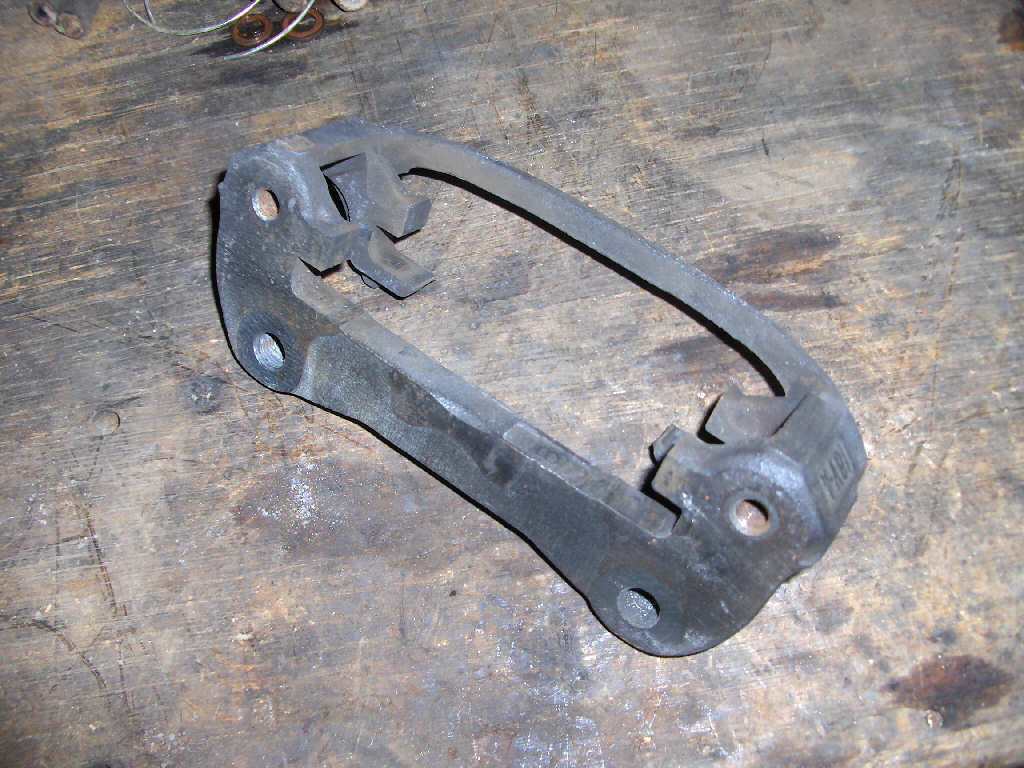
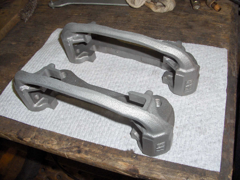
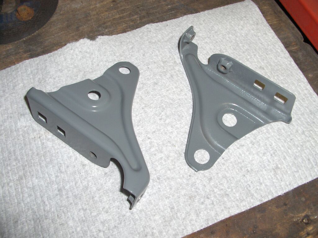
I also seem to be on a bit of a powder coating kick. So, I went ahead and powder coated my 1st generation Paseo brake caliper brackets and a few other brackets. The caliper brackets won't be going on the car right away since I still have the stock 13" steel wheels on it. However, I had them sand blasted and the powder coater was mostly setup already. I just decided to shoot them since I had the time. I also did a bunch of other brackets while it was rainy out this weekend. The black is matte black and the grey is a zinc rich primer.
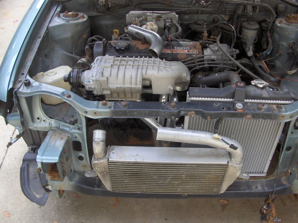
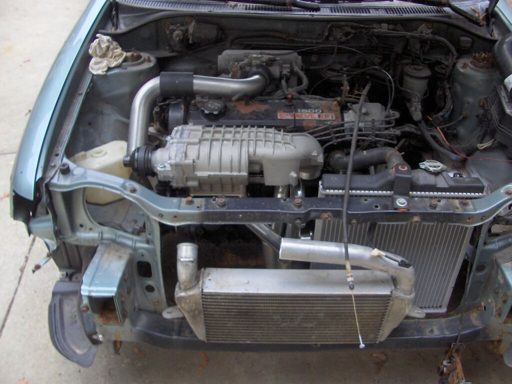
Before it started raining for the weekend, I did get some engine work done. I spent some good time at the local Autozone sorting through their radiator hose for use as intake piping couplers. I ended up picking up three molded tubes that should fit the bill. I got the mandrel bends cut up and welded ends on them and welded a bead on them as well to help hold the couplers on. I also cut the intercooler piping to where I wanted it. Here is the setup as it currently sits.
7/22/07
Alright, two weekend in a row for updates, not bad. Yeah, thankfully I've had time to work on the car lately. Its been very nice. Not only have I had time, but the weather has been great for working outside. You can't ask for much more.
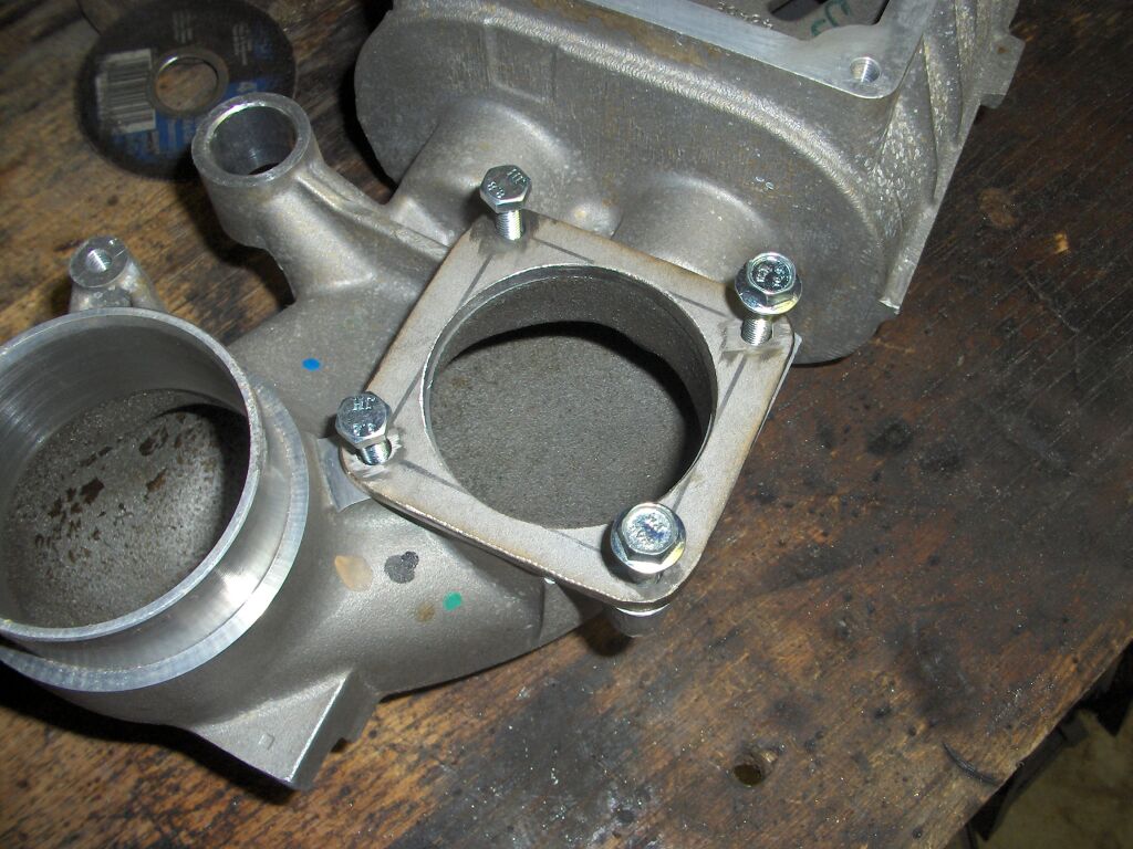
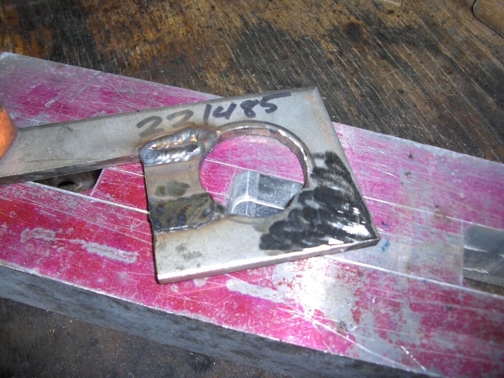
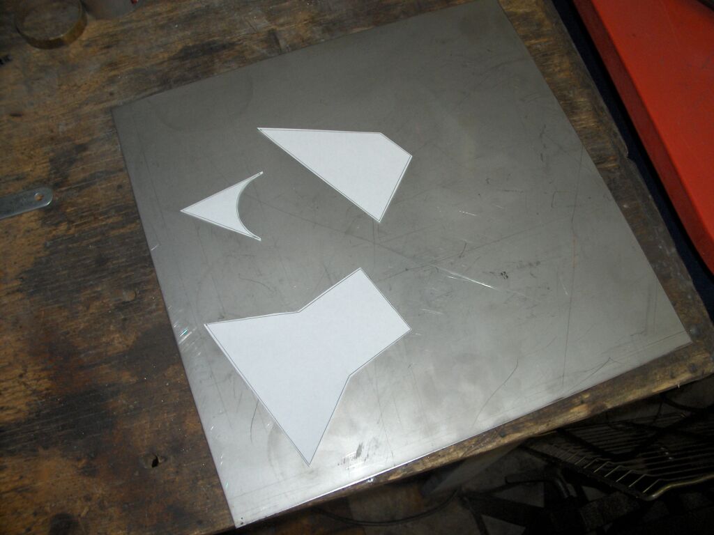
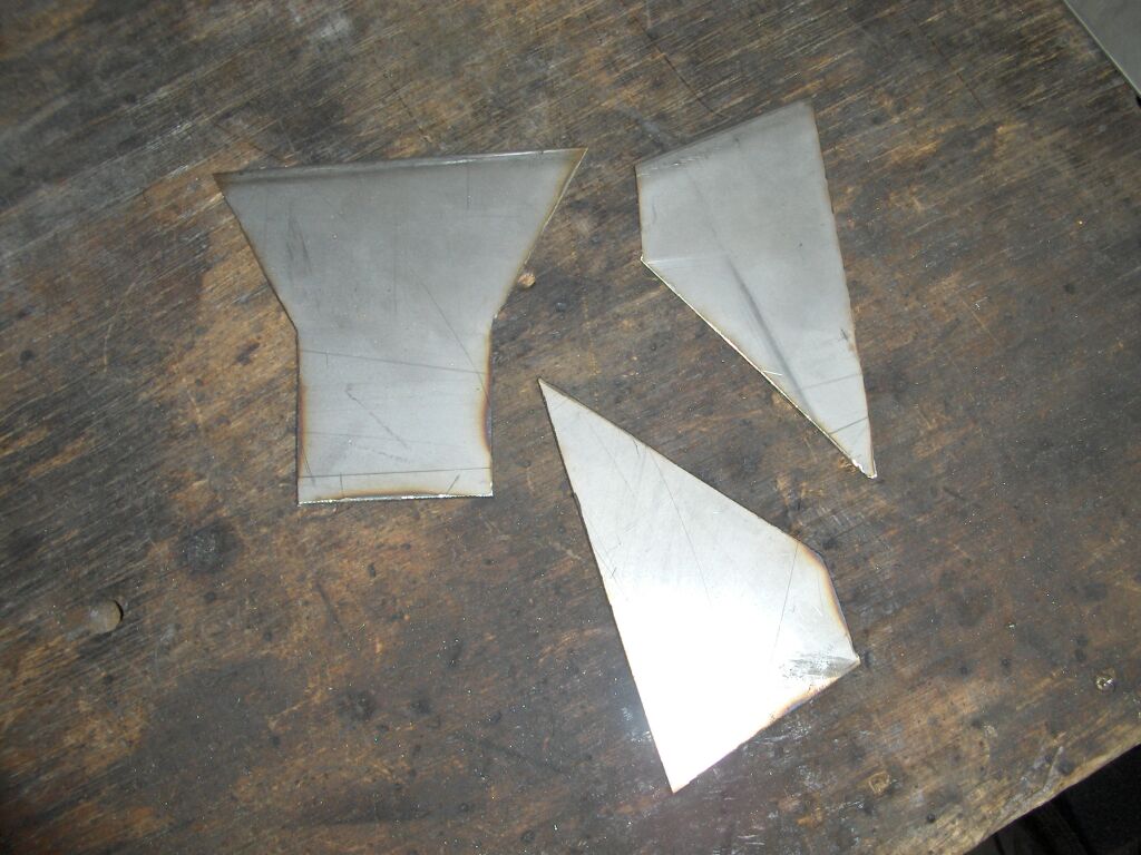
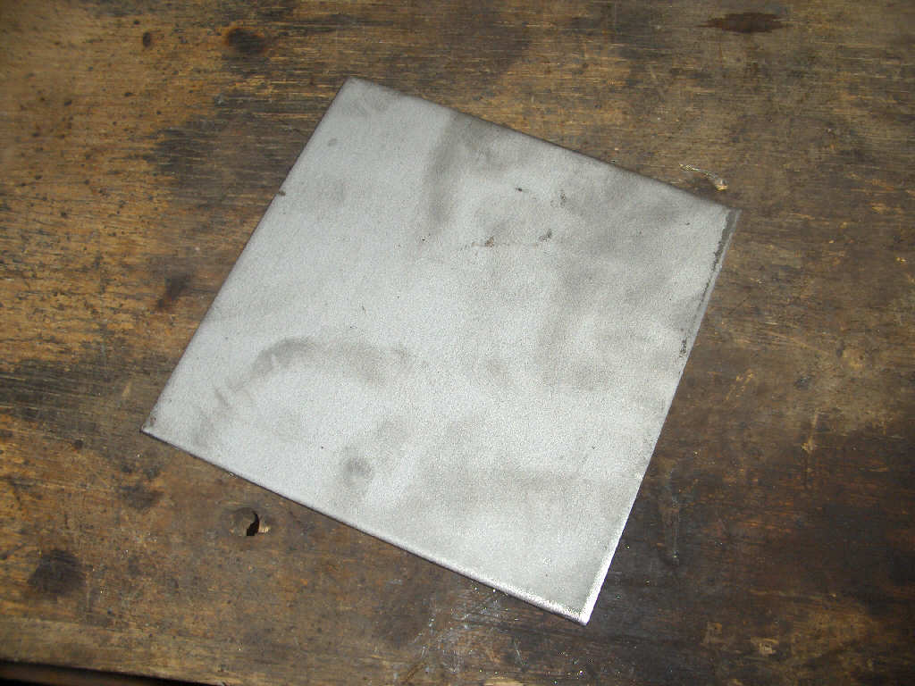
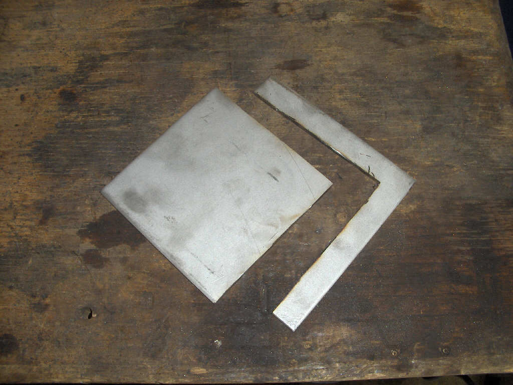
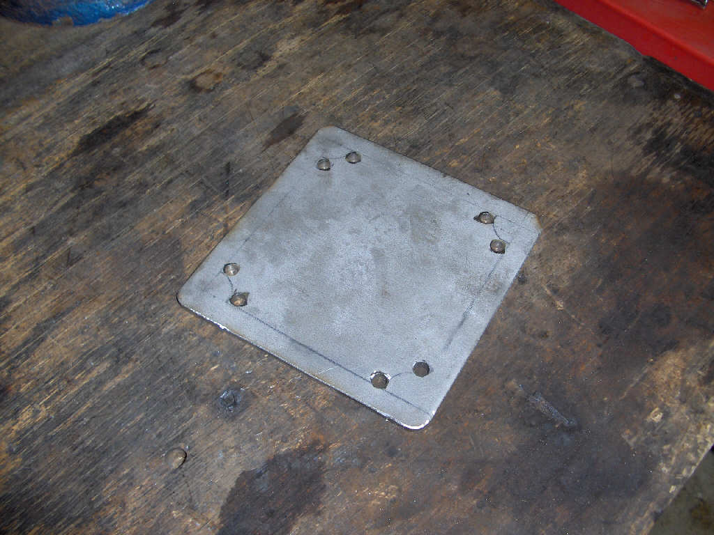
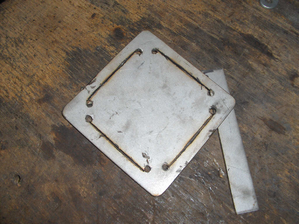
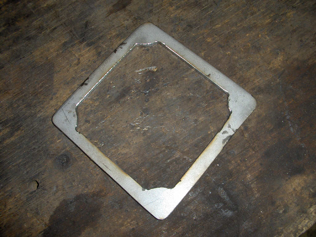
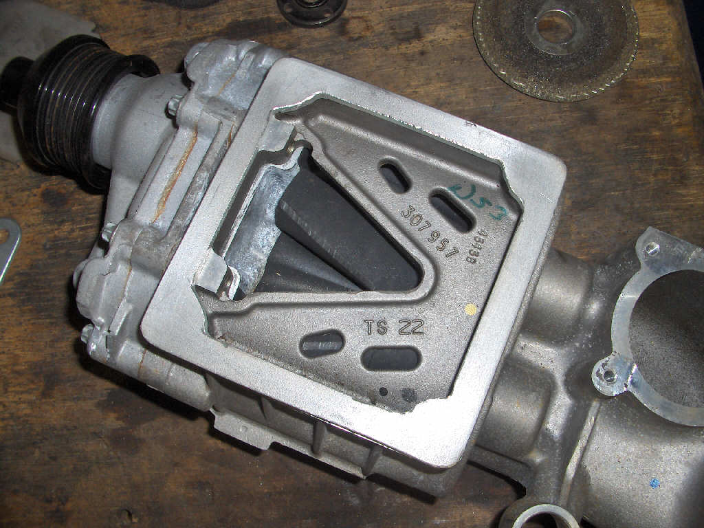
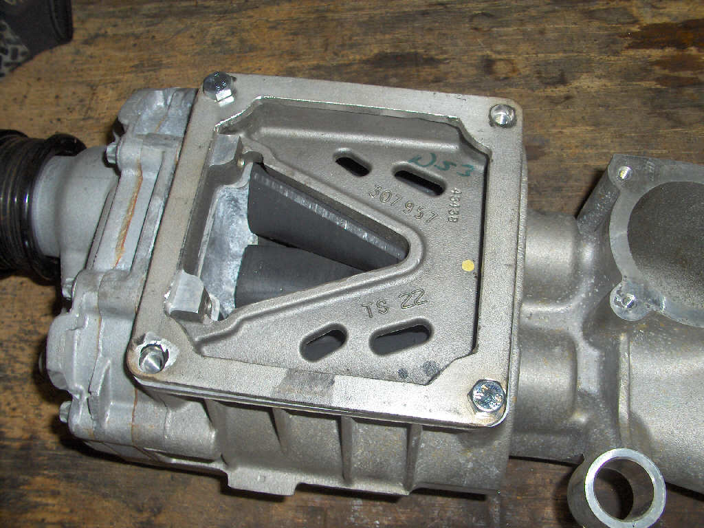
On to the good stuff now. I ended up getting a descent amount done this weekend. First off I took Saturday to work on the supercharger outlet flange. That got finished up as you can see below. I was originally thinking about sending this out for waterjet or laser cutting as it is 3/16" thick 304 stainless steel. Instead, I decided to take a crack at it with my angle grinder and drill press. The end result is pretty good if I must say so.
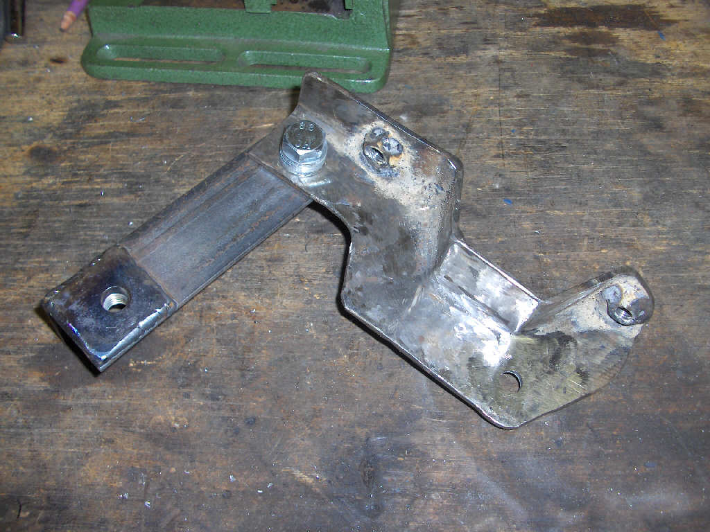
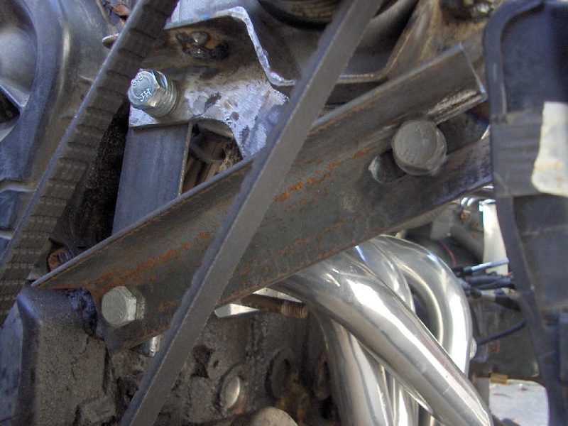
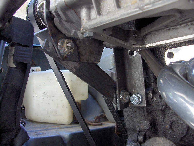
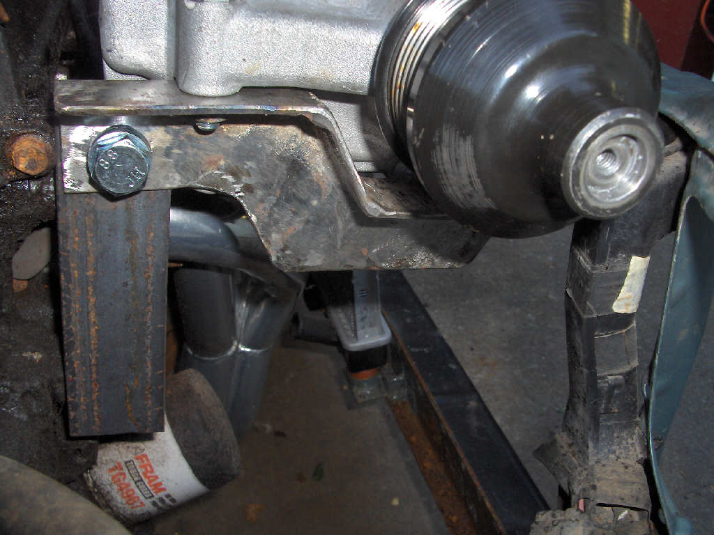
After finishing up the supercharger outlet flange I started working on the right side supercharger mount. It went very smoothly and here are the results. Its a bit rough yet, but that'll be fixed in time.
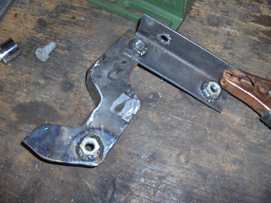
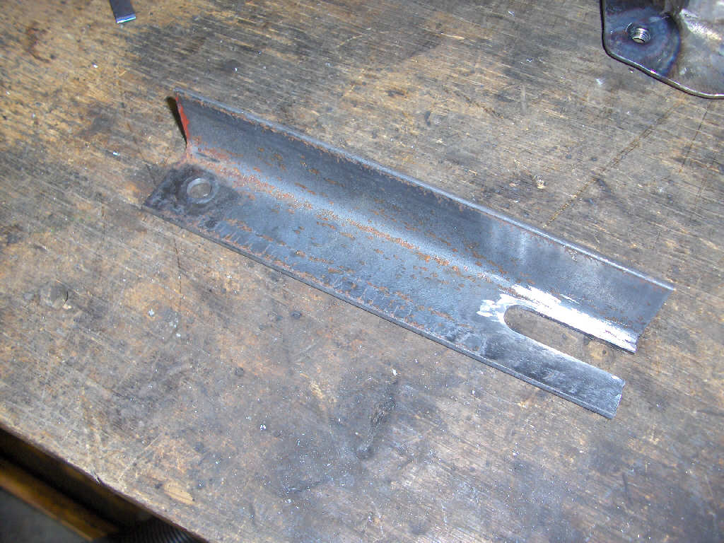
Next on the list was finishing up the left side supercharger mount's tension adjustment. It is farily simple and went pretty smooth. I'm still wanting/thinking about incorperating some sort of mechanical tightener on it to make things easier. However, that will have to wait.
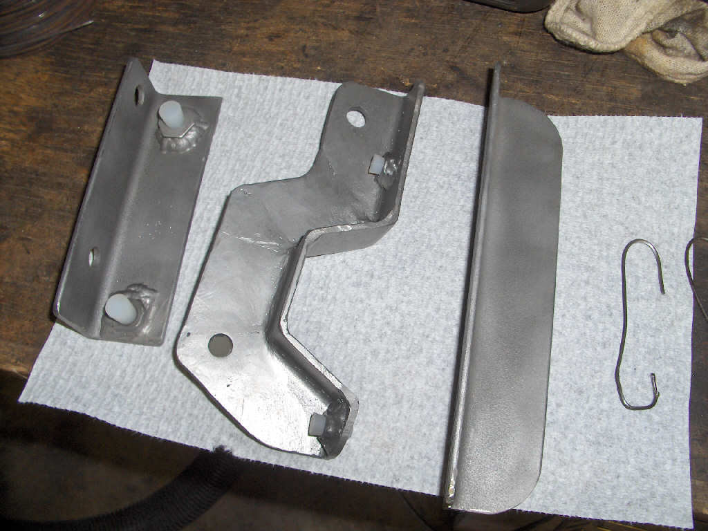
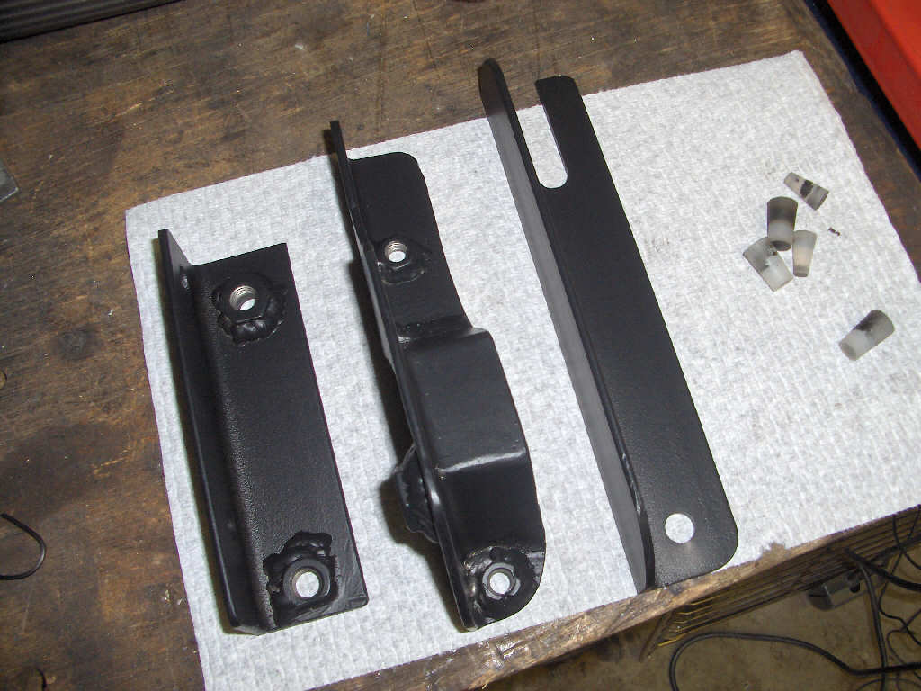
Last, but not least, it is time to sand blast and powder coat the mounts. I went with a matte black so as to look somewhat factoryish. I only got the three pieces done due to compressor problems.
7/15/07
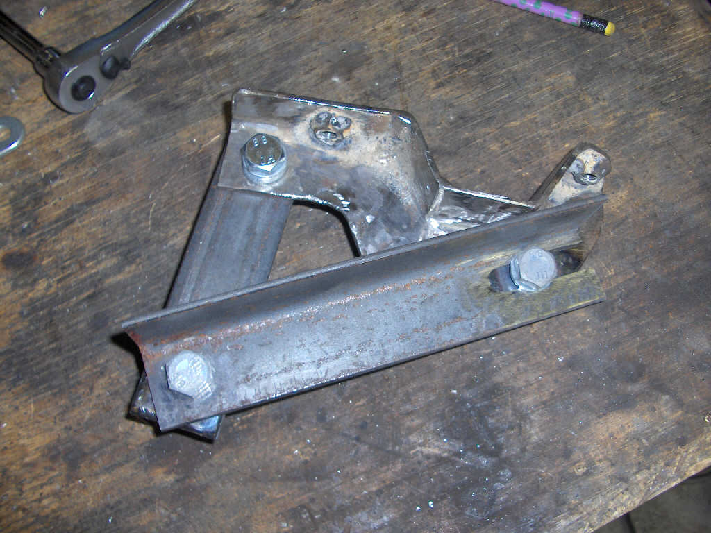
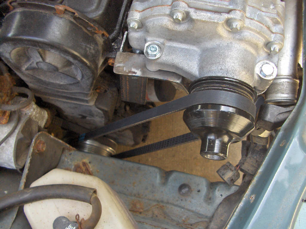
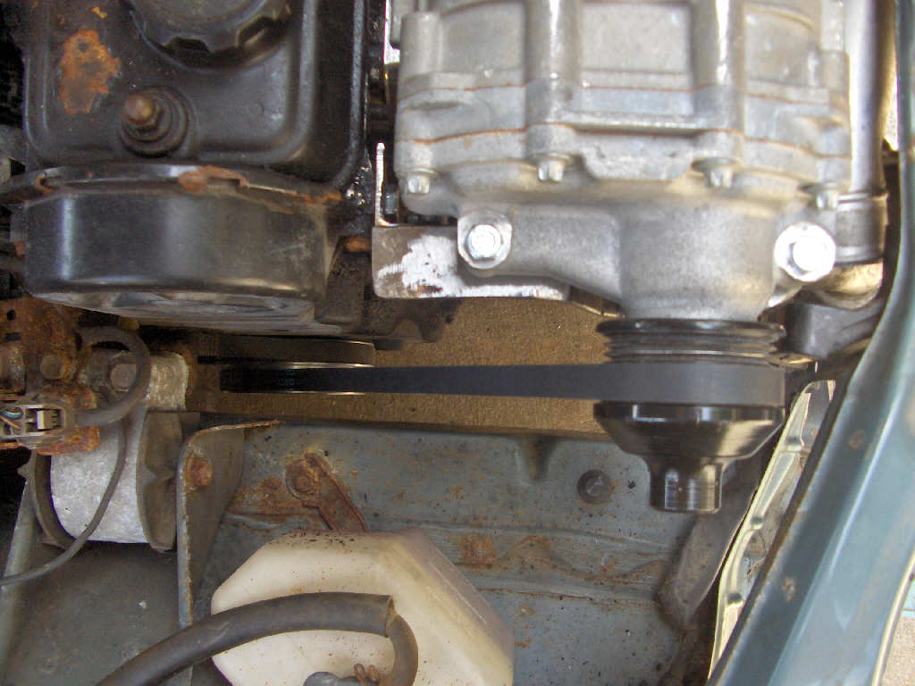
After a long and busy winter and spring I bring updates. I got to work on the supercharger mount this time around. I have to say, its really quite tricky trying to make all this fit, make it easy to take apart, and work correctly. After some hard thinking I decided to make a supercharger mount that would pivot the entire mount to tighten the belt (similar to our alternator belt tension adjustment). This means that I won't need a tensioner pulley to make in addition to the supercharger mount. So, I started fabricating it up. Here are the pictures so far.
After I knew the supercharger was where I wanted it to be I measured up how long of a belt I would need, and ran out and got one from the local autoparts store.
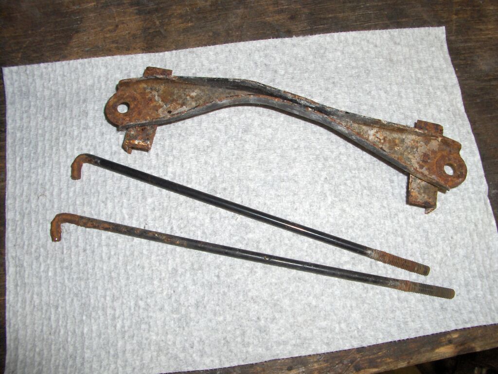
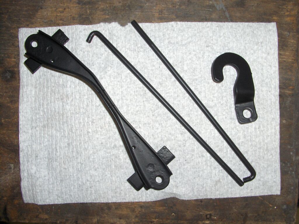
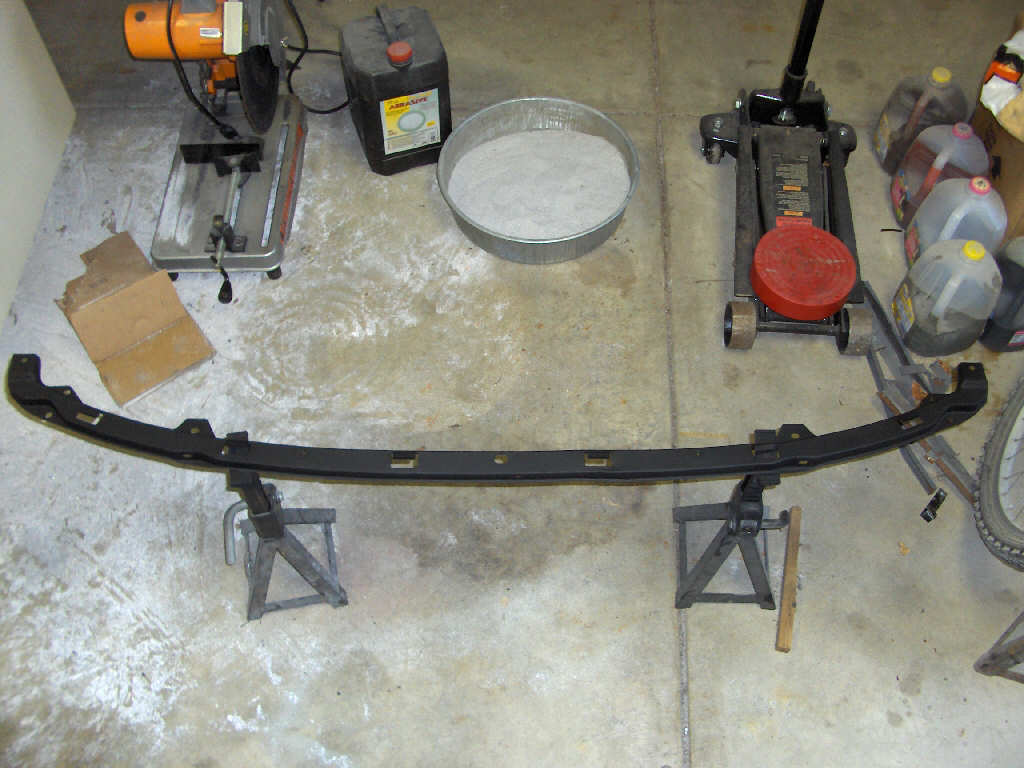
I also took some time to straighten and repaint the bumper cover upper mount. Too bad you'll never see it again. I think the flat black looks great.
Another thing that has progressed over these past few months since the last update is that I figured out how I will be controlling the dynamic boost. I'm not too surprised, but I found a company that makes a device that already does this. Magnuson Products has bypass valves that use a vacuum actuator to control boost pressure. You simply run a vacuum line to your intake plenum and when the vacuum drops to about 6 in/hg the valve starts to open. By 0 in/hg it is fully open. This allows the supercharger to not build pressure (thus not suck power) at partial throttle. It also allows a smooth transition from 0 to whatever max psi simply by pushing the gas pedal further.
11/22/06
Wow, another month has wisked on by. However, we have a good update update.
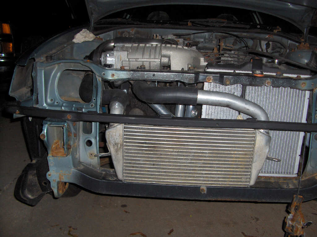
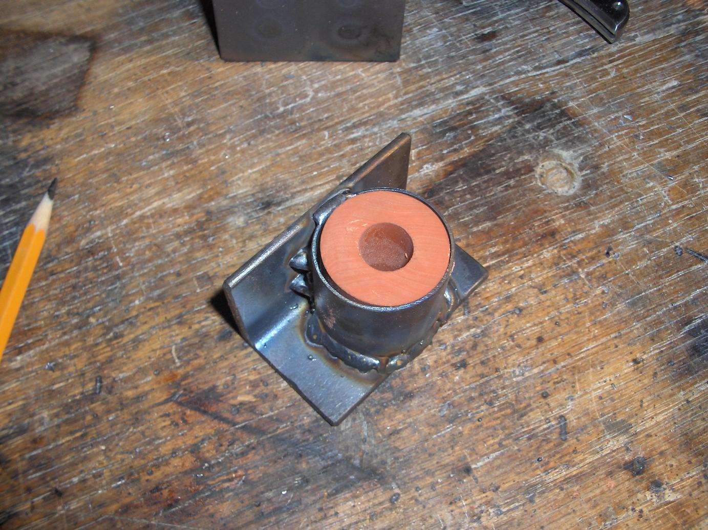
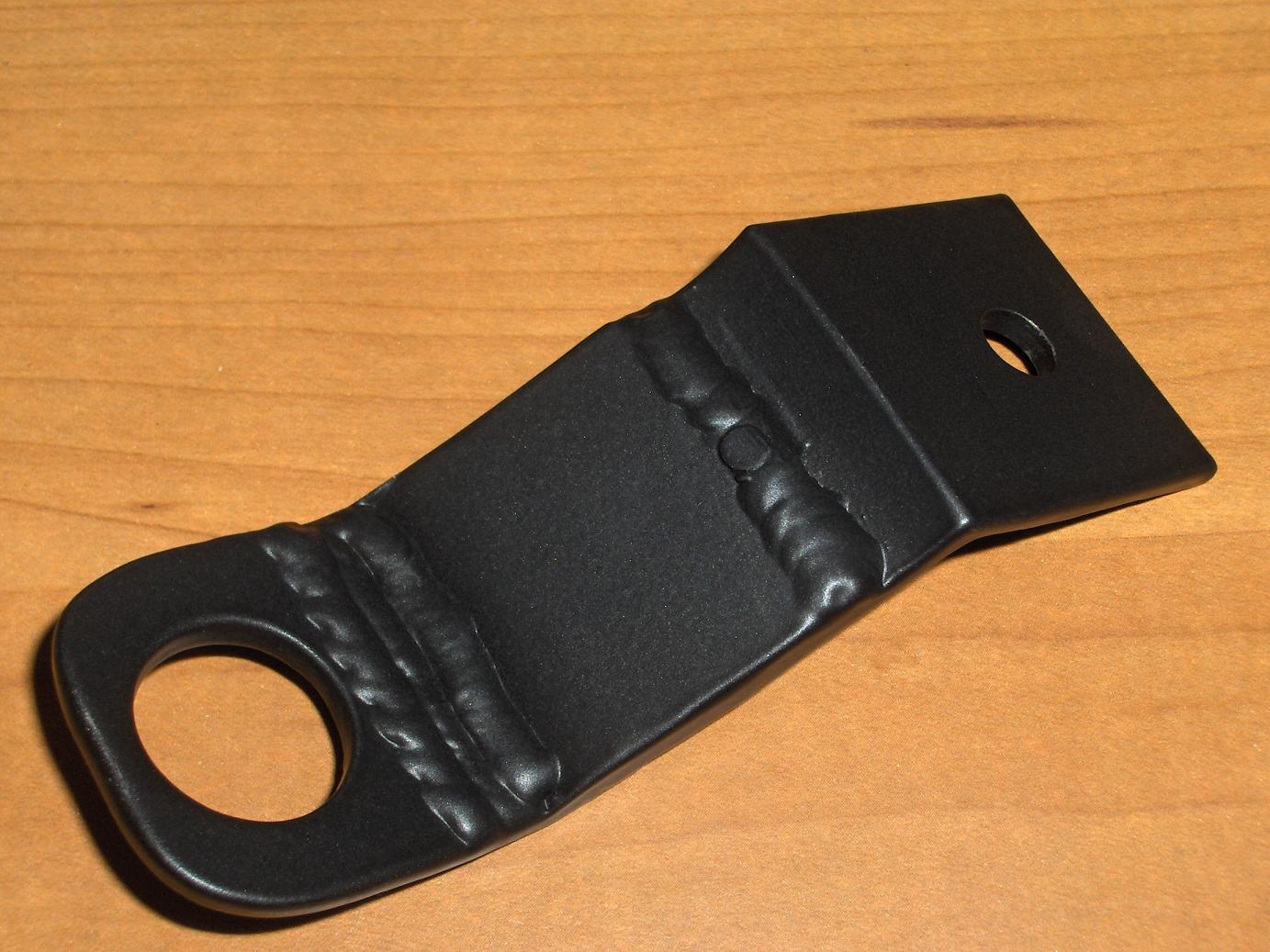
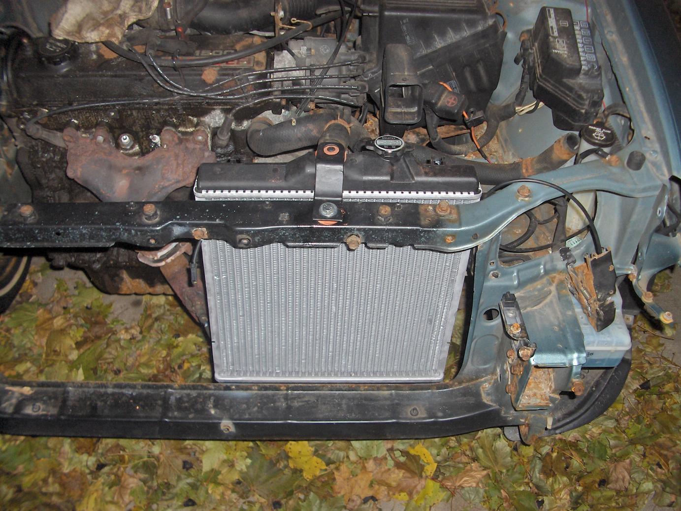
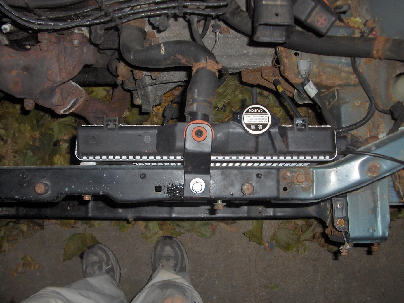
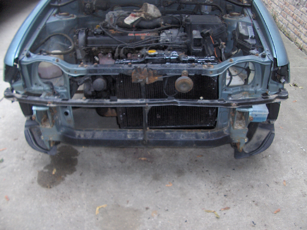
I ended up finding out that the '87 Tercel radiator was a bit too long to comfortably fit the supercharger where I want to put it. So, I went and found myself an even smaller one. Welcome 1990's Honda Civic radiator. The Civic radiator has the same hose fitting sizes and is a few inches shorter than the Tercel radiator. I was also able to pick it up for fairly cheap off ebay. Anyway I made new lower mounts for it and welded them to the frame after cutting off the old Tercel ones. Afterwards I made the top mount which was just two pieces of angle iron lap welded together. I only really mention this because it was the first item I got to use my new powder coating setup on. It came out beautifully. The color is matt black. Below we have the lower and upper mounts.
With the radiator now in place I know how much room I'll have for the header and the supercharger. Luckily the radiator is totally out of the way for both of these items and I shouldn't have worry about anything but the upper and lower front frame support.
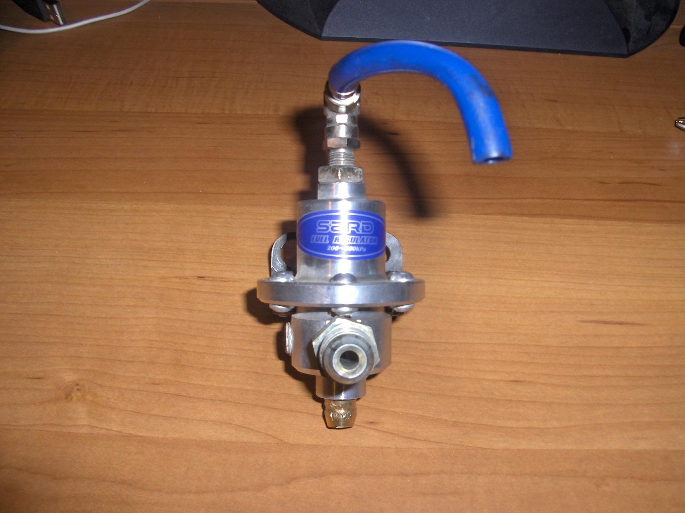
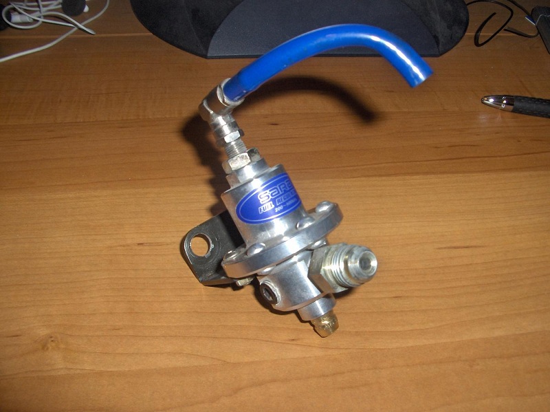
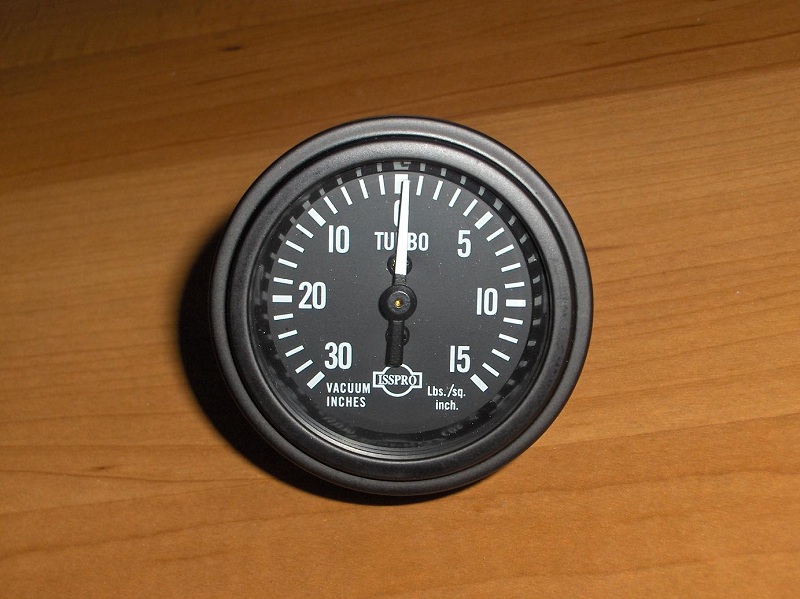
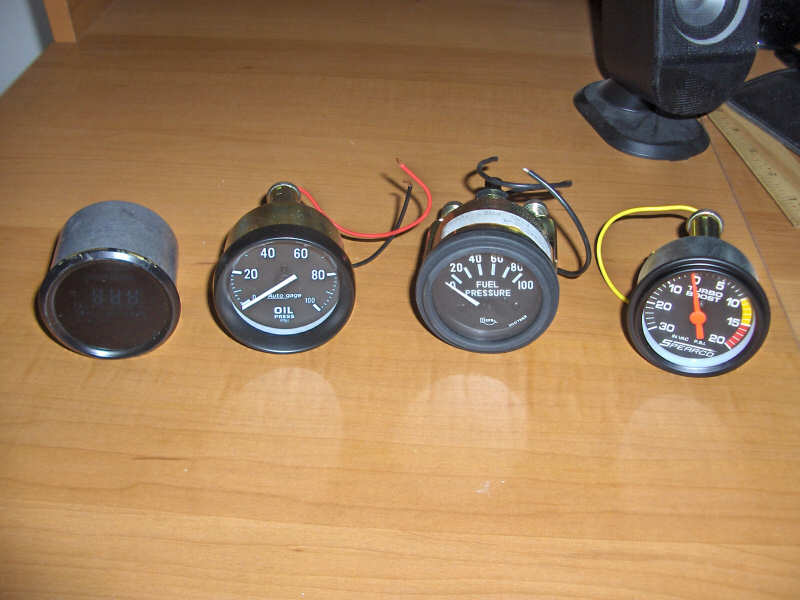
To button up this update I picked up a used SARD fuel pressure regulator off ebay for an very reasonable $60 with a fuel rail adapter. My wife was also nice enough to pick up this nice new Isspro boost/vacuum gauge for me to replace the other Spearco boost/vacuum gauge. I like it more because it matches the stock gauges much better.
8/28/06
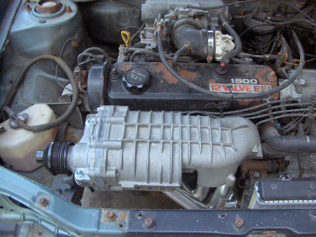
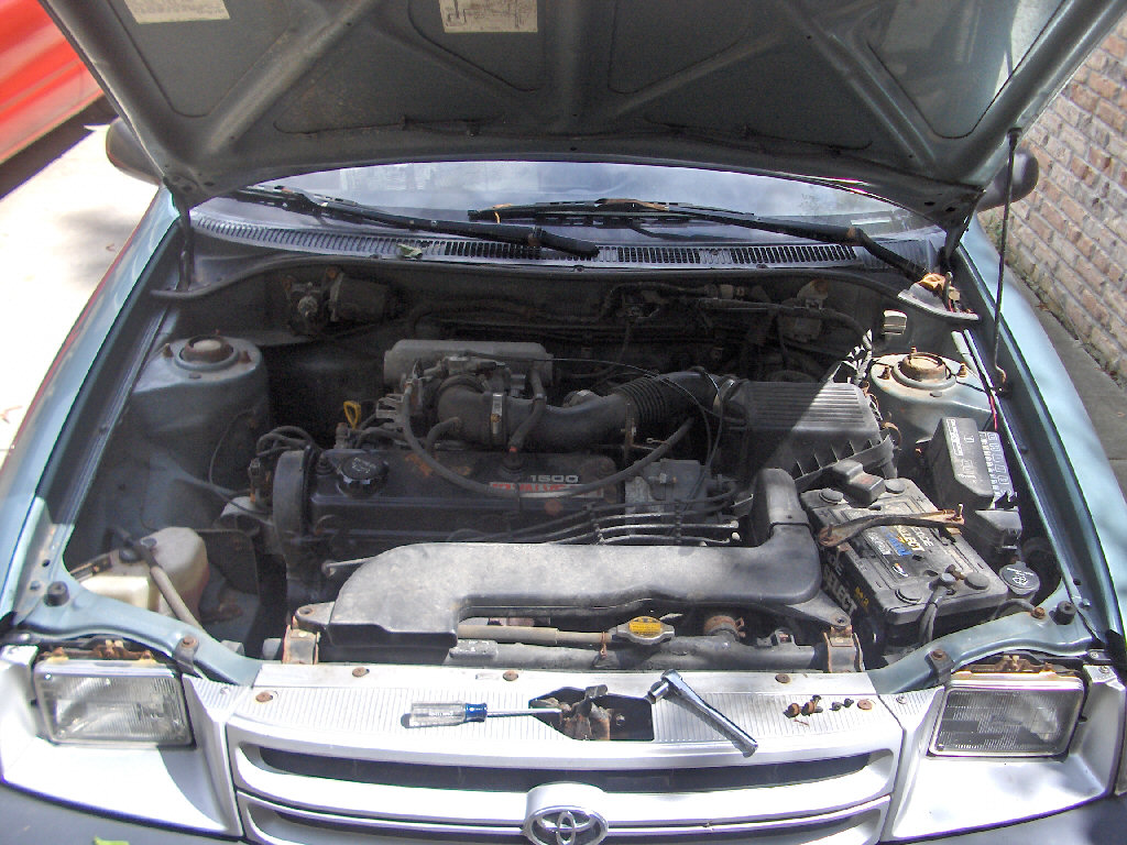
Alright, a good meaty update this time. Well not really meaty but at least some actual work is being done! I started pulling things apart to plan on how to mount the supercharger. To sum it up I'll use Julian Edgar's words, (Autospeed journalist) "Nothing is surer than death and taxes than the shrinking that occurs of your engine bay in the time between spotting the blower at the wreckers and taking it home to install it." So, yeah... its going to be tight. I'm currently debating two different locations for the supercharger. The original location I had thought of would have been to the left of the exhaust manifold pretty much directly in front of the oil filter. That spot may still work but I am finding out getting the exhaust manifold/header around the supercharger is going to be a good trick should I put it there. The other spot is directly up from there. That would place the supercharger just a little bit above the exhaust manifold/header. There isn't an overabundance of room here either. The problem here is if the engine rocks too much the supercharger will hit the underside of the hood. Theres also not a lot of room under the supercharger to route the intake plumbing since its so close to the exhaust manifold, and that brings not only clearance but heat into the equation.
Other than that you can see below the disassembly that has taken place in the past few weeks. Everything seems to be going fairly well that way. I found out the years of love taps by other cars has smashed my bumper up fairly badly so I'll have to replace that. The small bent up bar you see in the lower picture isn't the bumper, its the bumper cover holder and as you can see its bent up too.
7/31/06
This time we have one of the final pieces of the puzzle. I finally nabbed an intercooler off ebay. It should have been here a lot sooner but the previous seller I bought one from didn't feel the need to ship it to me after I paid. In any case here is the intercooler of choice for this project. Its from a late 80's Starion.
7/13/06
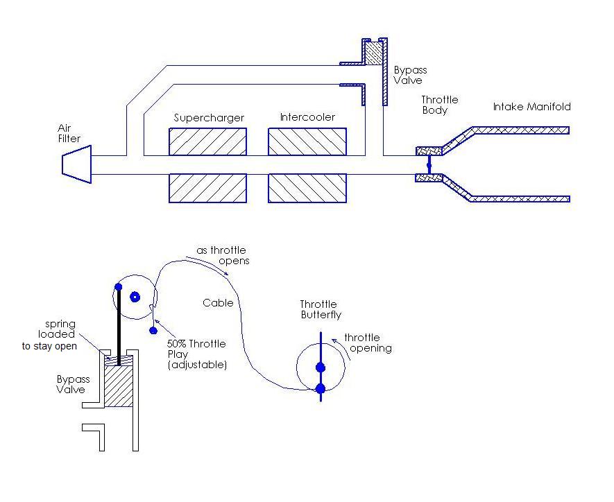
I think we are due for another update here. I've been thinking of how I am going to control the boost and integrate this dynamic boost I've been talking about. I think I have come to a conclusion. At the least this is where I am starting out. The dynamic boost will be controlled mechanically via a bypass valve. This valve will be controlled inversely by the throttle opening. That means at idle (throttle closed) the bypass will be fully open recirculating all the air and developing no boost pressure. At full throttle it will be fully closed creating maximum boost. This all seems simple enough. But, now comes the tricky part, the intermittent. I would like boost to start building at about 50% throttle. This would allow me to cruise in normal driving and even drive fairly normally without touching boost pressure. This will retain the good gas mileage if driven off boost situations such as highway traveling. After that 50% throttle the boost will start to increase until the throttle is at 100% and the bypass is fully closed. This is how the system will behave.
Now, to find a way to do this. I am choosing to control the bypass valve mechanically. This just seems the easier route especially considering my limited knowledge of electronics. It won't be as tunable but hopefully won't need to be. To achieve this it will actually be farily simple. I will attach a cable to the throttle body's pulley, and it will pull the valve shut as the thottle opens. There will be adjustable play in the system to allow for that first 50% of the throttle not closing the bypass. The specifics are not yet set in stone. I still don't even know what I'm going to be using as a bypass valve. I am thinking maybe a modified blow off valve, but I'm not sure yet. Below is a basic diagram of how the system will be laid out and work.
6/27/06
Time for a little update here. Its been nearly a month and not much has really been done. I have gotten the correct pulley ratio selected. Oddly (and conveniently) I am going to be using an ASP crankshaft pulley to power the supercharger. This actually ends up giving me slightly more boost than I need but that shouldn't be a problem as long as the bypass valve is working properly.
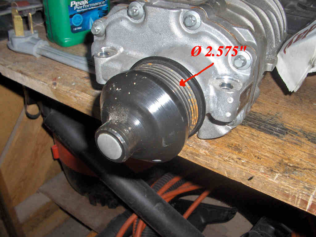
So, let me explain how I came up with the correct pulley diameter. First, I decided that at maximum boost I wanted to run was right around 10 PSI of boost. This should be a safe amount of boost to run on the 'ol 3E-E. So knowing that, I then used Ugabuga's Engine Performance Calculator. I calculated that at peak RPM the engine would need right around 265 CFM to produce 10 PSI of boost. Using the picture below which is from Eaton's website I then calculated that at maximum engine RPM the supercharger will need to be spinning at right around 9000 RPM to give me my 10 PSI. Maximum engine RPM on the 3E-E is right around 6000 RPM. So that means I need a pulley that will give me a 1:1.5 ratio. I then looked at which pulley would be easier to modify. The M62 pulley had no easy way of removal at quick glance. So, I measured both and found that the M62 pulley was 2.575 inches in diameter. Now we really can't calculate turn ratios with a diameter, so we have to convert that into a circumfrence.
2.575 diameter = 8.090 circumfrence (remember 2*PI*R to get circumfrence)
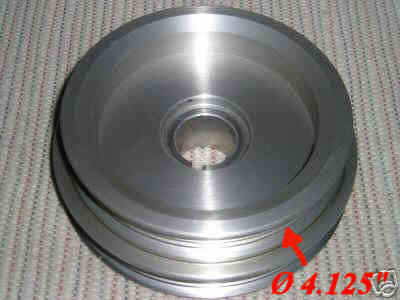
So, I need a pulley with a circumfrence of 1.5 * 8.090" = 12.135" to get my 1:1.5 ratio. Lets go backwards and make that a diameter again. This gives me a crankshaft pulley diameter of 3.863. I compared this with ASP's pulley diameter of about 4.125" and decided that it was probably close enough. In the end I end up with a turn ratio of 1:1.6. This should give me a maximum boost of just over 11 PSI. That, and I don't have to make a custom pulley! That is a pretty good deal in my book.
5/30/06
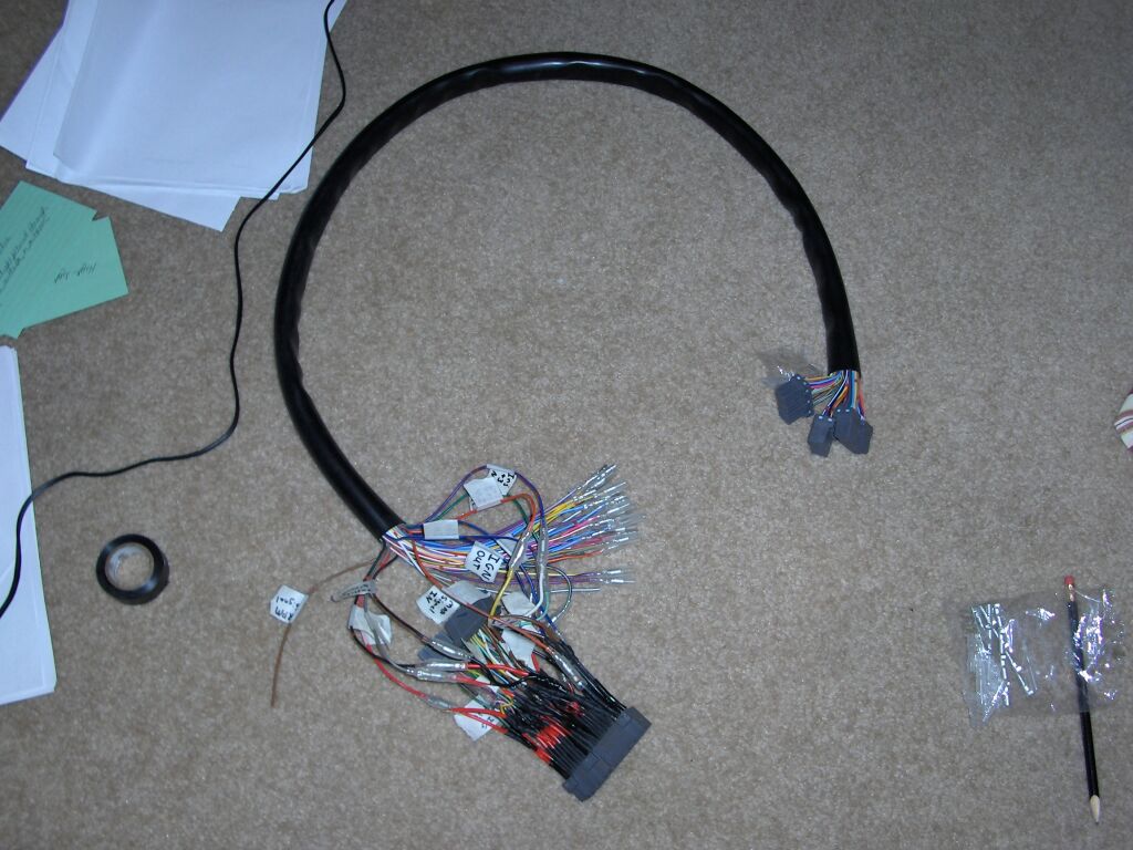
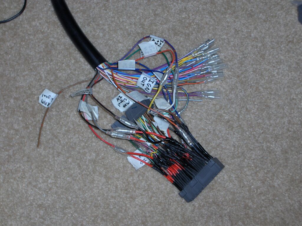
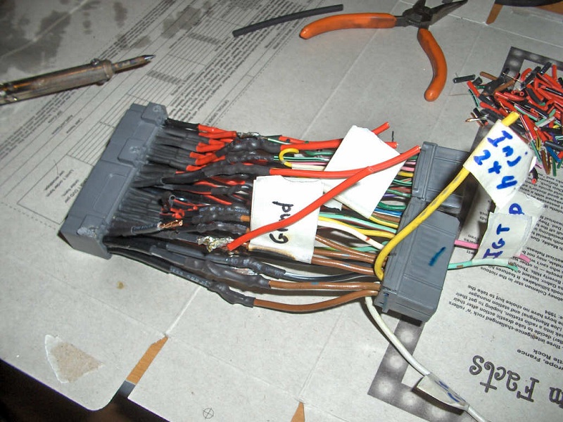
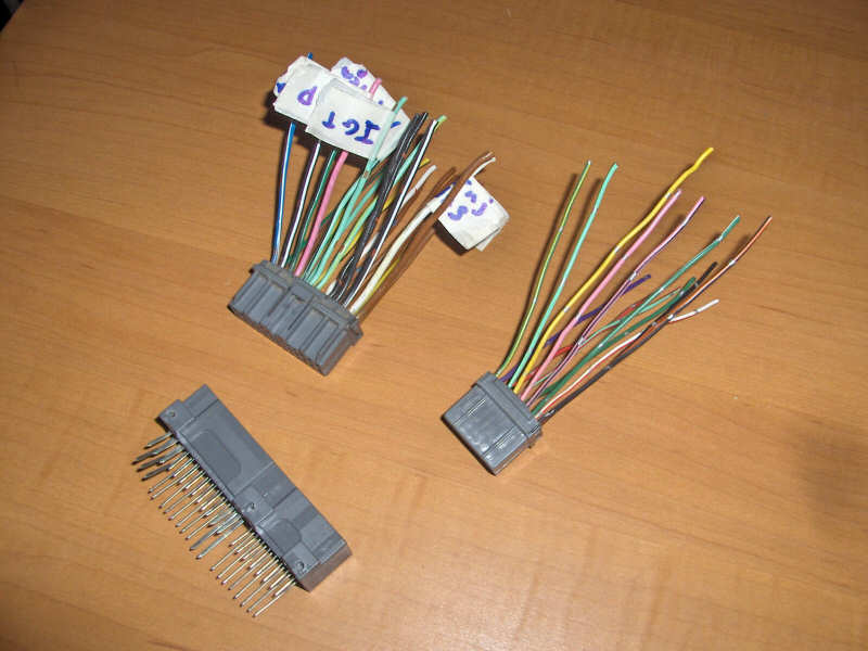
This is just going hand in hand with the new article written. The E-manage Ultimate plug and play harness is finished. I should now just be able to plug one end into my ECU and the other end into the existing harness and the E-manage will be hooked up. I can't wait to get it in the car. Unfortunately, I have a lot of other things to do before this will happen. In the mean time I have to find another intercooler. The jerk of an ebayer that I bought my Starion intercooler from hasn't shipped it, and its been TWO months now. Of course I've filed claims against the seller. We'll see where that takes me. Anyway, as usual pictures of the harness are below.
5/17/06
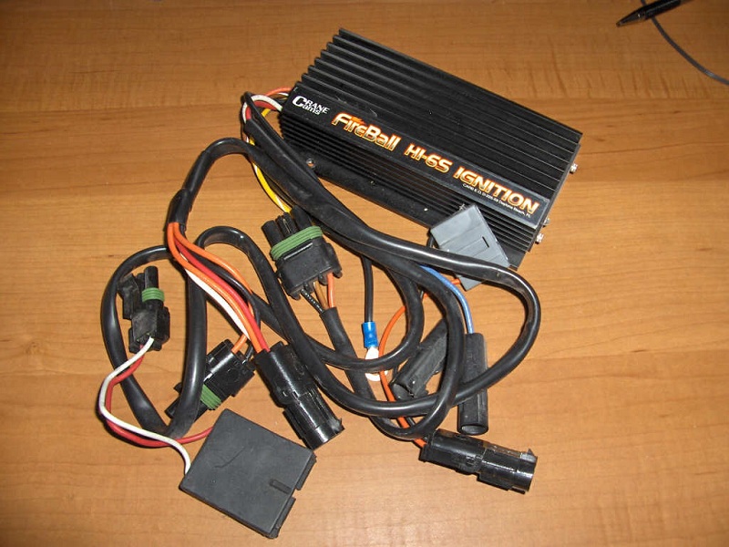
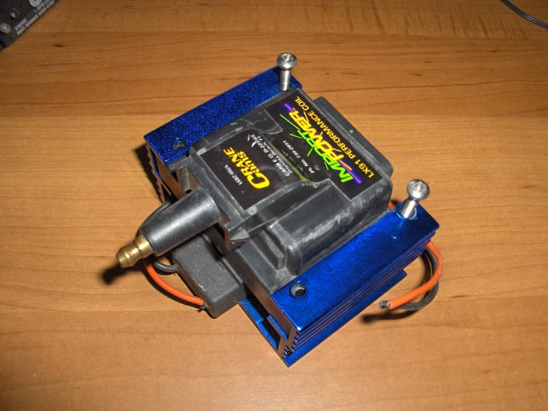
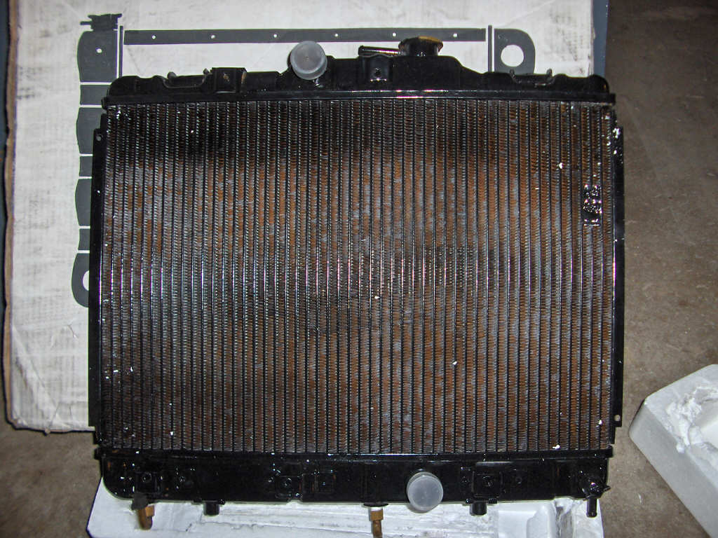
A few things have progressed since the last update. I have recieved my 1987 Tercel automatic radiator. This should provide the necessary clearance to run the supercharger's plumbing to and from the intercooler. I also remembered that I have a Crane Cams HI-6S ignition system along with a LX-91 coil. These will be added amongst the things to add to the car. They should help out the engine effeciency and performance.
Also, I have pretty much figured out what diameter pulley I will be using now to achieve the CFM that I want the supercharger to produce. A special thanks to Ugabuga on Tercel Online's forums for creating a nice excel document to help with this problem.
The progress on the dynamic boost is sending me in circles. I haven't yet found a good way of figuring out how I want to control it. However, the choices are getting narrowed down.
In any case, here are pics of the new parts. Left to right we have a Crane Cams HI-6S ignition controller, Crane Cams LX-91 ignition coil, and then we have the 87 automatic Tercel radiator.
5/9/06
Well, the project has begun. I have no doubt that this will take quite a while to all come together. A lot of research has been done and a lot more still needs to be done for this to work the way I want it to. The goal is for a nice torquey engine. Most gains are to be made in the low RPM range although I think there will also be very nice gains in the midrange and high end as well. I have no doubt I'll run into lots of problems. In all honesty, I just want to get the 95 Celica out of my garage so I can start working on it!
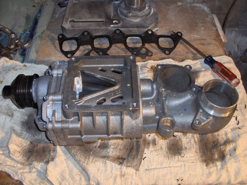
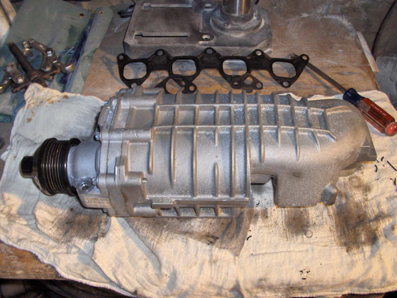
I have collected a nice list of parts that I think will get me started on this project. For the supercharger I chose the Eaton M62. This is Eaton's second smallest supercharger and is recommended for 2.5L to 4.0L engines. Obviously the 3E-E doesn't live up to those displacement numbers. So, I will need to make some changes. Most important is spinning the supercharger quite a bit slower so it doesn't push too much air. I am thinking about making a special crankshaft pulley for the supercharger to get it spinning exactly how fast I want. I am also aiming to make this system with what I like to call dynamic boost. Basically you can change the boost pressure as you wish anytime on the fly. This will help with gas mileage as well.
Here is a list of the main parts I am planning on using:
Eaton M62 supercharger from a Mercedes C230 Kompressor
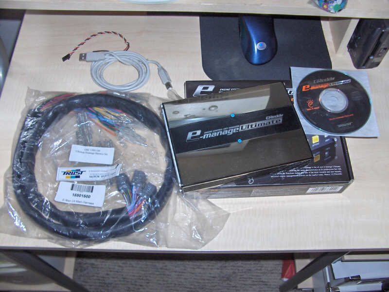
Greddy E-manage Ultimate
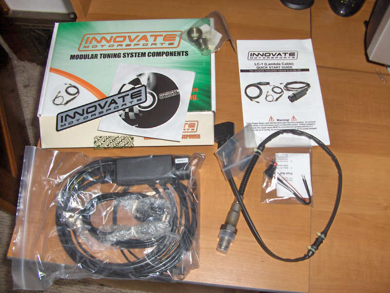
Innovate LC-1 wideband O2 controller
Starion intercooler or MKIII Supra intercooler
7M-GE 315 cc/min injectors
Custom exhaust header
I'm sure this list will change, but that is what I have in mind for the time being.
Here are some pictures of the parts I'm starting out with. The intercooler is on its way yet. Left to right is the Eaton M62 supercharger, Greddy E-manage Ultimate, 3E-E wire harness pigtail & connector, Innovate LC-1 wideband controller, and my gauges.