BACK
ACIS Activation Options
Written by: Daox
Proper activation of the secondary runners on the 5E-FHE's dual runner intake manifold is key to producing the most torque possible. Without proper activation the manifold is not being used to its fullest potential, and lots of power is being lost. Lets see how we can activate them correctly.
For those with a 5E-FHE ACIS intake manifold and no 5E-FHE ecu to speak of, how do you control the opening of the secondary runners properly? This is a very important function, and without the use of it the ACIS manifold isn't nearly as useful. So, lets look at some ways to activate the runners properly.
ACIS Operation
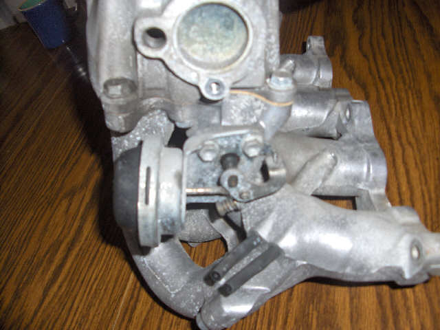
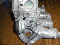
Lets first get some information on the manifold itself though. We need to learn and understand how it operates before we can come up with a good way to control it. The first thing to know is that the secondary runners are opened and closed by a vacuum actuator. This setup is very simple as you can see below. The actuator is hooked up to an arm which opens and closes the secondary butterfly valves.
The next thing we need to know is how the actuator works. At normal atmospheric pressure (0 psi), the runners are open. With vacuum going to the actuator, the runners shut. To be more specific the runners start to open at -3 psi, and by 0 psi they are fully open.
So, what does this mean? This means that if we run this intake manifold without any sort of vacuum switching valve between the actuator and the vacuum source the runners will snap open anytime you go to wide open throttle (WOT). This is not desireable. At lower rpms there simply isn't enough airflow to warrant the opening of the secondary runners. The result will be a loss of power.
ACIS Activation For Naturally Aspirated Engines
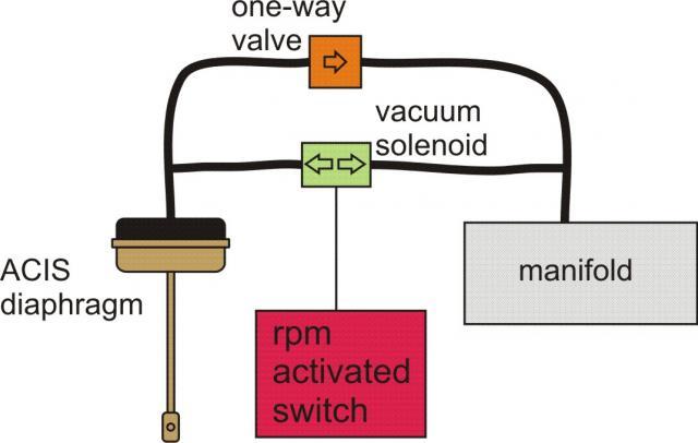
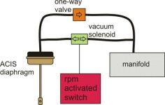
So then, how do we make the runners open up only at WOT and at a set rpm? Well, thats what we're here for, and the answer isn't very hard. The diagram below (drawn by paseo92) shows a good setup for a natrually aspirated engine. It immitates the 5E-FHE ECU's control system (stock setting is reportedly around 3800 rpm). In order to ensure that the vacuum actuator can only 'see' atmospheric pressure above a set rpm, we insert a vacuum switching valve in the vacuum line between the actuator and vacuum source. This valve is controlled by an rpm switch. Above a set rpm the valve opens up and the actuator will be able to 'see' atmospheric pressure if there is any, and open up. Below the set rpm the valve will stay closed and the actuator will only see vacuum. The one-way valve (check valve) is only there in case the switching valve leaks, and is not absolutly necessary if the valve seals properly. Yet, they cost next to nothing, so its not a bad addition.
Alright, we know how to do this. Now, what can we use for parts?
First off we need a vacuum switching valve or solenoid valve. This should ideally be a normally closed valve. It also must be rated for 15 psi of vacuum, and it must have fittings for vacuum hose. The fix here is easy. All cars these days use these valves to control vacuum to one thing or another. One simply must be found that is normally closed. It should meet all the other requirements since it was being used on an engine.
Next, we need an rpm activated switch. There are a few options for these. We'll discuss these below.
Use your piggyback or aftermarket ECU to control switching. Many aftermarket ECUs and piggyback ECUs have optional outputs for controlling things such as this. Look through your manual to see if yours has the capability.
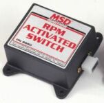
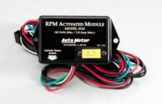
MSD makes a rpm activated switch. It uses rpm modules or pills that you must plug into the unit to get the desired switching rpm. This means if you want to play around with what rpm to activate the secondary runners, you need to buy a bunch of these modules. They set the switch in incriments of 200 rpm. If you want finer adjustment, you'll have to look elsewhere. Autometer also makes a similar unit. They both sell new for around $80, and the rpm modules are sold seperatly.
Summit Racing also has an rpm activated switch. It uses dip switches to set rpm values. It can set your rpm switch in incriments of 100 rpm (except it can not activate at 1900, 2900, x900 etc rpm). This switch sells for around $40.
The final alternative would be to make your own switch. If you do a bit of googling you can find electronic diagrams for making your own switch out of parts you can probably get from the local Radio Shack. Most won't like this option, but it'll definitly save you a bit of cash as electronic components aren't real expensive.
ACIS Activation For Forced Induction Engines
Adding boost pressure puts a little kink in our previous setup. Its not really harder to put this setup together, but its definitely different, and it isn't quite perfect. In order to keep the system simple we have to sacrifice something. In this case, we are going to sacrifice load sensing. This means that when you hit your open rpm, the runners will open no matter how much throttle you are giving it. However, this really isn't a big deal as we'll see.
Since this setup is different, lets take a minute to rethink how this should go together. In our previous setup the vacuum actuator sensed engine load. At near 0 psi it opened up indicating a high engine load. Well, in this case, 0 psi does not always indicate high engine load, so it really can't be used to sense load properly. It can now only be used as an open/close switch.
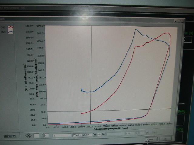
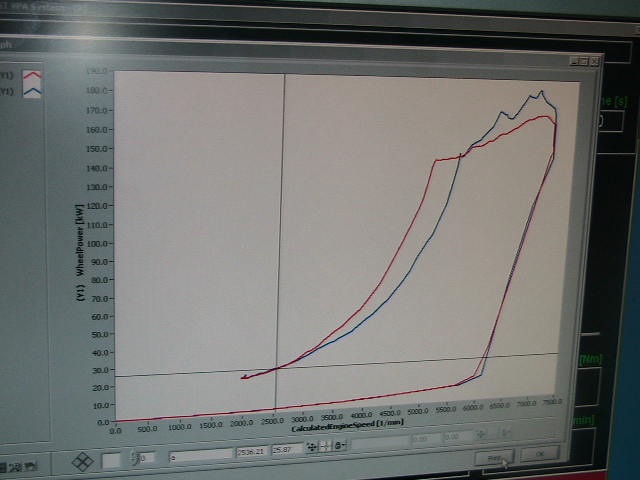
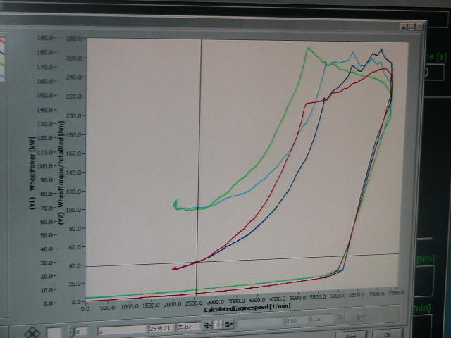
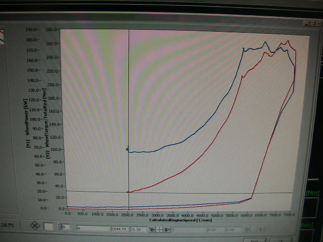
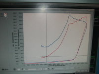
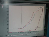
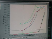
The good news is, according to the only testing I've ever seen done, the rpm at which the secondary runners should open in a turbocharged is higher than it would be in a naturally aspirated 5E setup. Lets took a look at this example. Hoodey did some testing with his turbo 5E setup. He did a dyno run with only the primary runners open (pic 1), then he did a run with both primary and secondary runners open (pic 2). When we overlay these two dyno runs over each other (pic 3) we can see massive gains from keeping the secondary runners closed until a fairly high rpm. In this case it is around 6400 rpm. This is why no load sensing is not going to be a big deal. If you are not at wide open throttle and are up to 6400 rpm you're obviously not looking for peak power, so we're not going to worry about it.

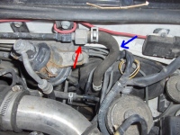
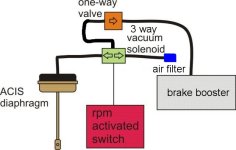
Alright, so you want that great low end power, and that high end peak power. Well, we can do that, and here is how. First off we run a vacuum line from the actuator to a three way vacuum solenoid. One line from the solenoid will go to an air cleaner. The other line will go to a check valve, and then spliced into the vacuum line going to the brake booster between the booster and check valve. See the first picture to see the vacuum line to tap into. The blue is the line, the red is the check valve.
This setup, along with the rpm switch of your choice, will allow proper actuation (for the most part) of the secondary runners on the ACIS intake manifold.
It should be mentioned that each engine setup will require a different switching rpm. Ideally, you will want to do what Hoodey did and make two dyno runs with the manifold at its different states. Where the horsepower lines cross from each dyno run is your switching rpm.
Of course, these aren't the only ways to operate the manifold properly. You could use an electronic actuator and control it with some sort of switch too. However, these are the setups I've seen that seem to be easiest to work with. If you have another build option, contact me and I can add it to this page.
BACK